Tutorial: Inertia Relief Analysis
Tutorial Level: Beginner Define a force using components and run an analysis with inertia relief.
Overview
Inertia relief is a numerical method used for analyzing unconstrained structures. A typical example is an aircraft in steady flight where the lift, drag, and thrust loads are balanced by gravity acting on the mass of the total aircraft. This acceleration due to gravity is equal and opposite to the acceleration that would result for the unconstrained structure.
At a component level, with inertia relief it is possible to analyze a part in isolation if the loads at the interface points are known or can be measured/calculated and the part can be considered to be in static equilibrium.
- load setup
- running inertia relief
| Location | Shock | Pivot | Axle | |
|---|---|---|---|---|
| Force | Fx N | -2352 | 980 | 1372 |
| Fy N | 3211 | -3700 | 489 | |
| Fz N | -635 | 645 | 0 | |
| Moment | Mx N*mm | 0 | -104867 | -278 |
| My N*mm | 0 | -188238 | 779 | |
| Mz N*mm | 0 | 0 | -7998 |
Apply a Component Force to the Shock Mount
-
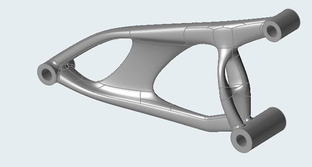
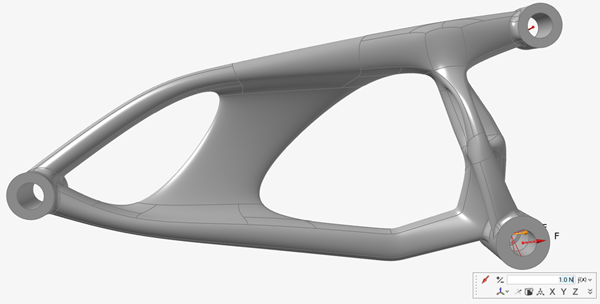
Double-click the 0.0_swingarm_IR_FEA.x_b file to load it
in the modeling window.
This is a solid model of a single-part motorcycle swing arm.
- Make sure the display units in the Unit System Selector are set to MMKS (mm kg N s).
-
On the Structure ribbon, click the Force
 button in the Loads tool group.

Tip: To find and open a tool, press Ctrl+F. For more information, see Find and Search for Tools. -
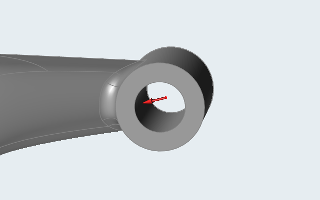
Click to apply the force to the hole center of the shock mount.
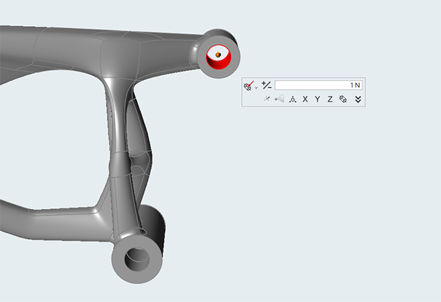
-
Click Vector Mode
 on the
microdialog to switch to Component Mode, and then click the
on the
microdialog to switch to Component Mode, and then click the  chevron
to expand it.
chevron
to expand it.
-
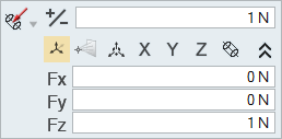
Enter the following values:
- Fx: -2352 N
- Fy: 3211 N
- Fz: -635 N
- Right-click and mouse through the check mark to exit, or double-right-click.
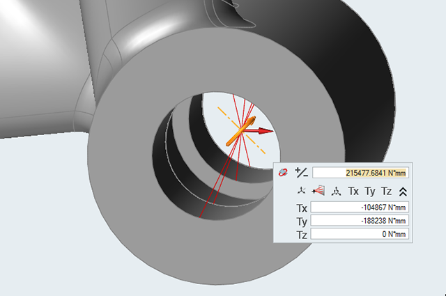
Apply a Component Force and Moment to the Swing Arm Pivot
- Zoom in on the swing arm pivot.
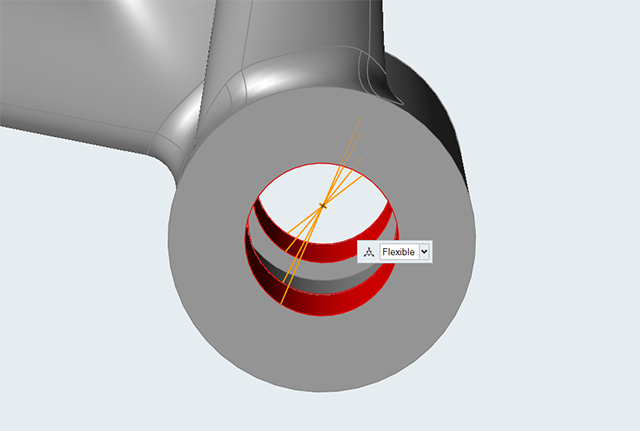
-
On the Structure ribbon, select the Connectors
tool.

Tip: To find and open a tool, press Ctrl+F. For more information, see Find and Search for Tools. -
Select the two faces as shown below to create a connector at the center of the
hole:
-
On the Structure ribbon, click the Force
button in the Loads tool group.
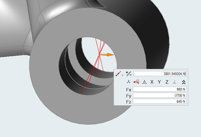
- Click the connector at the center of the hole.
-
Click
Vector Mode
on the
microdialog to switch to Component Mode, and click the
chevron
to expand it.
-
Enter the following values:
- Fx: 980 N
- Fy: -3700 N
- Fz: 645 N
-
On the Structure ribbon, click the Torque
 button in the Loads tool group.

- Click the connector at the center of the hole.
-
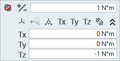
Click Vector Mode
on the
microdialog to switch to Component Mode, and click the
chevron to expand it.
-
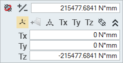
Enter the following values:
- Tx: -104867 N*mm
- Ty: -188238 N*mm
- Tz: 0 N*mm
- Right-click and mouse through the check mark to exit, or double-right-click.
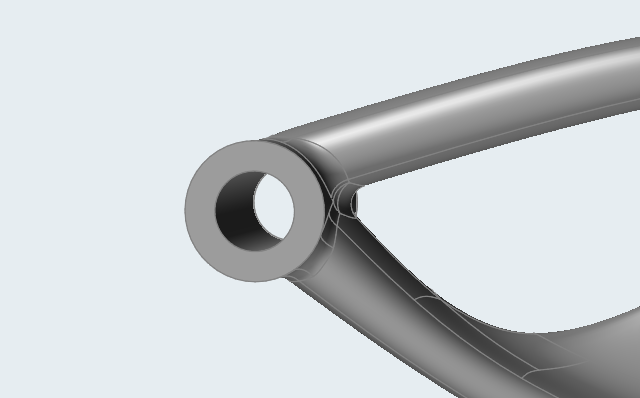
Apply a Component Force and Moment to the Center of the Axle
-
Zoom in on the center of the axle.
-
On the
Structure ribbon, click the Force
button in the Loads tool group.
-
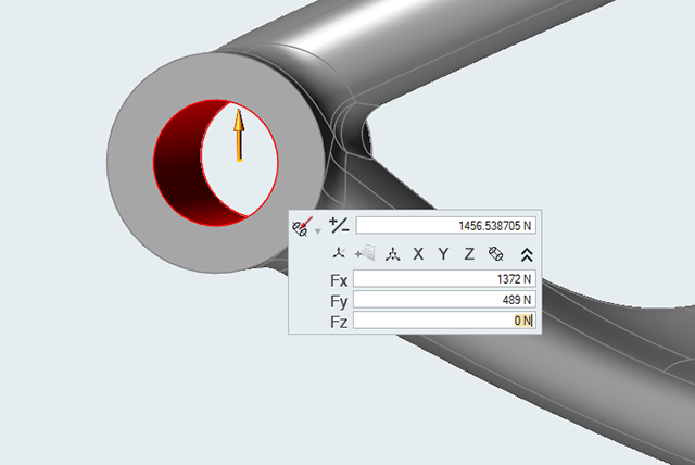
Select the face as shown below to apply a force to the hole center of the
axle.

-
Click
Vector Mode
on the
microdialog to switch to Component Mode, and click the
chevron
to expand it.
-
Enter the following values:
- Fx: 1372 N
- Fy: 489 N
- Fz: 0 N
-
On the Structure ribbon, click the Torque
button in
the Loads tool group.
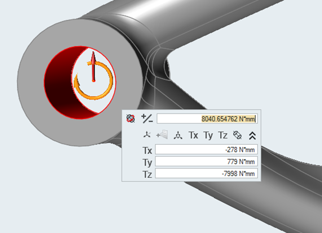
-
Select the face shown below to apply a torque to the hole center of the
axle.

-
Click Vector Mode
on the
microdialog to switch to Component Mode, and click the
chevron
to expand it.
-
Enter the following values:
- Tx: -278 N*mm
- Ty: 779 N*mm
- Tz: -7998 N*mm
- Right-click and mouse through the check mark to exit, or double-right-click.
Run an Analysis with Inertia Relief
-
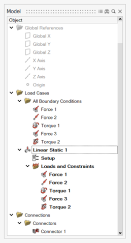
Press F2 to open the Model
Browser.
Note that a default linear static load case has been created containing all the created loads.
-
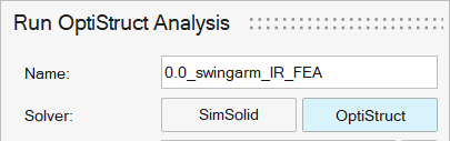
On the Structure ribbon, click the Run Analysis
 button in the
Analyze tool group and ensure
OptiStruct is selected as the solver.
button in the
Analyze tool group and ensure
OptiStruct is selected as the solver.

-
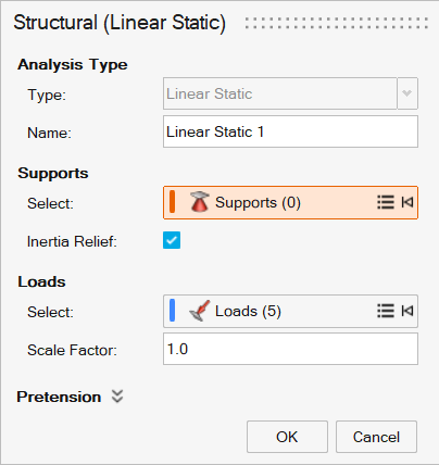
In the Model Browser, double-click Setup under the
Linear Static 1 heading.
The Structural (Linear Static) guide panel is displayed.
-
Select the Inertia Relief checkbox and then click
OK.
-
On the Structure ribbon, click the Run Analysis
button in the
Analyze tool group.
-
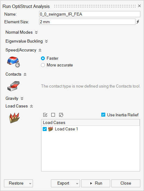
Run the analysis using the following settings:
- Change the Element size to 3.0 mm.
- Set Speed to Faster.
- Select the Linear Static 1 load case.
- Click Run to perform the analysis.
-
When the run is complete, select it in the Run Status window and click
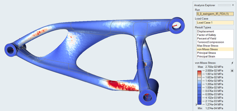
View Now to view the results.

Tip: You can also double-click the Results icon in the Model Browser to view results for a load case.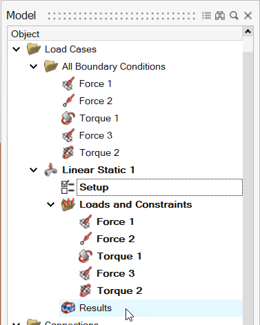
-
In the Analysis Explorer, select von Mises Stress from
the Result Types dropdown.
Note: Even without supports, the analysis runs as any imbalance in the loads is reacted by the inertia forces.