Double-click the Analysis_Contacts.stmod file to load it
in the modeling window.
Make sure the display units in the Unit System Selector are set to
MPA (mm t N s).
Important: Setting display units to MPA (mm t N s) will be
important for comparing analysis results.
Notice that the model already has a load case defined. Our objective for this
load case is to accurately simulate the transfer of loads from the torque
applied at the inside end of the bar to the bracket designated as the design
space.
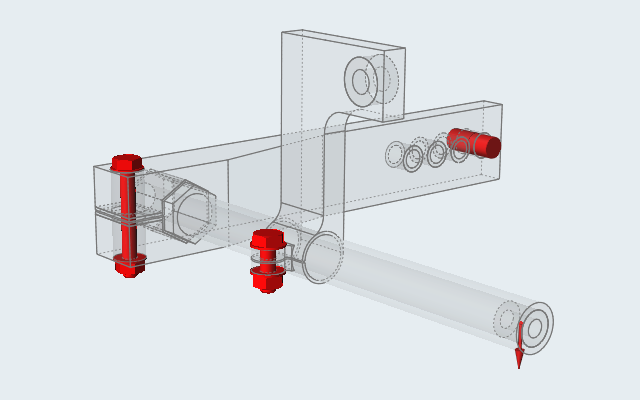
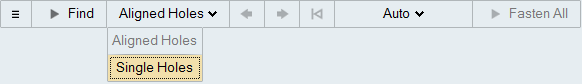
Create Nuts and Bolts in Aligned Holes
On the Structure ribbon, select the Fasteners
tool.
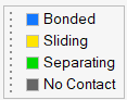
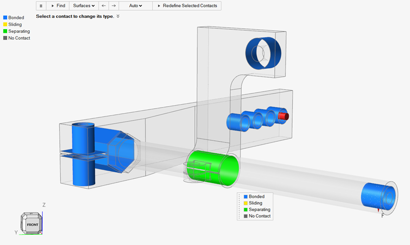
All of the contacts in this model are currently defined as bonded
contacts (default) and are shown in blue.
Click the contact where the bar touches the L bracket.
A microdialog appears.
Choose a contact Type from the dropdown list on the
microdialog to change the contact type.
Select Bonded if parts are bonded or glued
together.
Select Sliding if there is relative sliding
between the parts.
Select Separating if the relative parts can
separate.
Select No Contact if parts are close but you
don't want them to have contact.
Run the Analysis with Sliding Contact
While the Contacts guide bar is still active, click the contact where the bar
touches the L bracket and select Sliding in the
microdialog.
Right-click and mouse through the check mark to exit, or double-right-click.
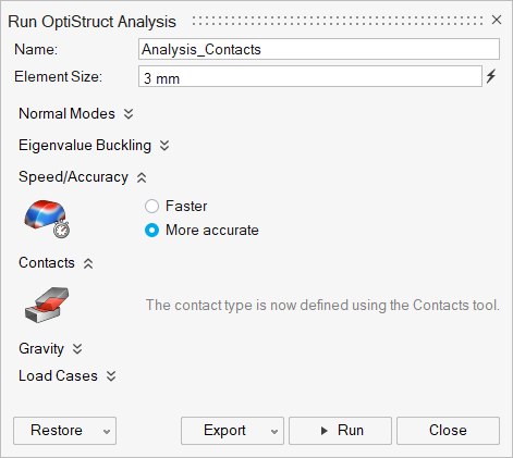
On the Structure ribbon, click the Run Analysis button in the Analyze tool
group.
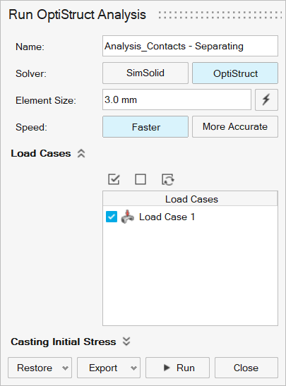
Run the analysis using the following settings.
Add Sliding to the run name.
Select OptiStruct as the solver.
Change the Element Size to 3.0
mm.
Set Speed to More
Accurate.
Click Run.
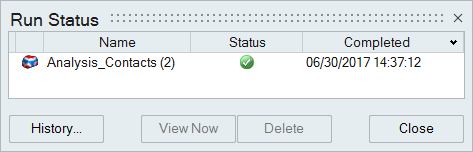
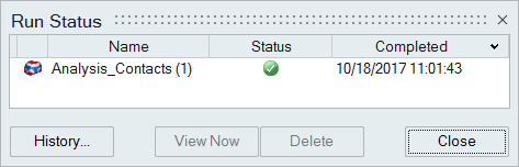
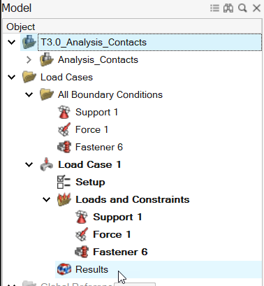
When the run is complete, select it in the Run Status window and click
View Now to view the results.
Tip: You can also double-click the Results
icon in the Model Browser to view results for a load case.
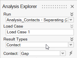
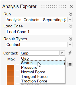
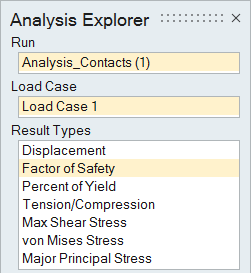
In the Analysis Explorer, select Factor of Safety from
the Result Types dropdown.
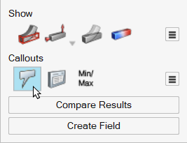
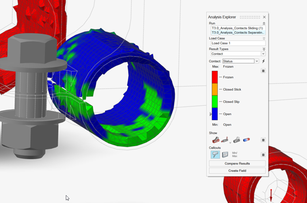
In the Analysis Explorer, select Show/Hide Deformed
State to show the deformed state of the model.
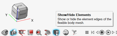
Select Show/Hide Elements in the View Controls to show
the finite element mesh.
Click the button on
the animation toolbar to review the analysis. Click the button to
pause the animation.
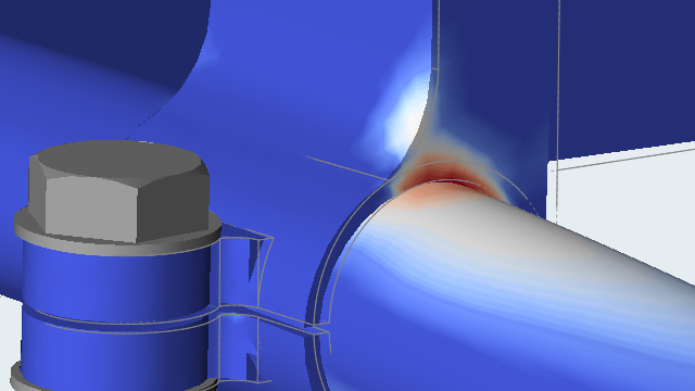
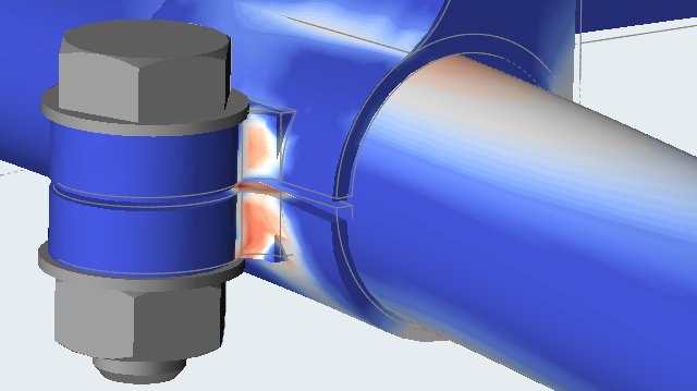
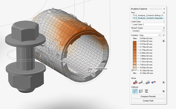
Notice that the L-bracket and the sway bar are acting as if they are
tied radially. This leads to an unrealistic stress in the L-bracket as the sway
bar should be allowed to open a gap.
Right-click and mouse through the check mark to exit, or double-right-click.
Note: With Sliding contact types,
you can run the model faster, but the results will not be as accurate.
Rerun the Analysis with Separating Contact
On the Structure ribbon, select the Contacts tool.


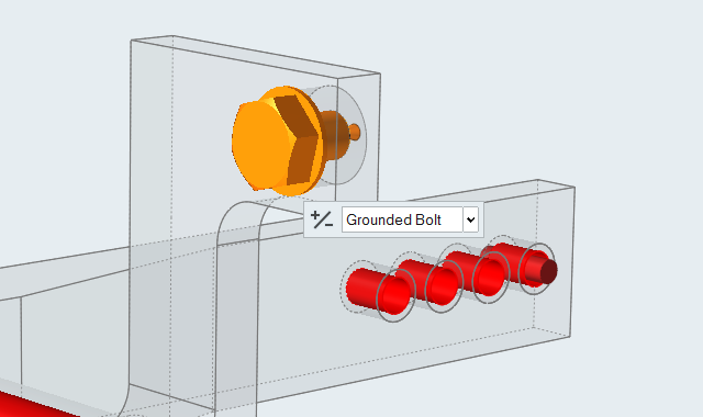
 on the guide
bar to create fasteners.
on the guide
bar to create fasteners.

 Tip: To find and open a tool, press Ctrl+F. For more information, see Find and Search for Tools.All of the contacts in this model are currently defined as bonded contacts (default) and are shown in blue.
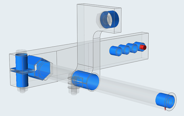
 button in the Analyze tool
group.
button in the Analyze tool
group.

 to show the deformed state of the model.
 button on
the animation toolbar to review the analysis. Click the
button on
the animation toolbar to review the analysis. Click the  button to
pause the animation.
button to
pause the animation.