Tutorial: Generating CAD from Optimization Results
Tutorial Level: Beginner Learn how to fit a PolyNURBS to a smoothed result.
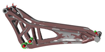
This tutorial starts with the results of a structural topology optimization applied to a mountain bike suspension component. The optimization was set up to maximize the stiffness of the component across two load cases using 15% of the designable material.
-
Explore the results with the shape explorer
-
Perform analysis directly on topology optimisation results
-
Understand the inputs for automated PolyNURBS fitting
-
Create and detail high-quality concept geometry
-
Prepare the model for analysis
-
Analyze the final concept
Optimization Results Exploration
-
Double-click the 2.0_Concept_Creation_and_Analysis.stmod
file to load it in the modeling window.
-
On the Structure ribbon, click the Show Optimization
Results button in the Optimize tool group
to view the Shape Explorer for the optimization that was previously run and
saved with the model.

This loads the topology optimization and opens the Shape Explorer.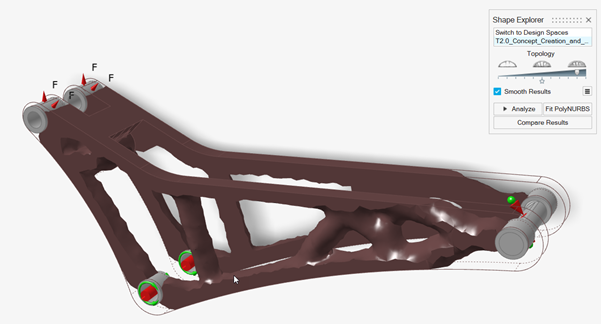
-
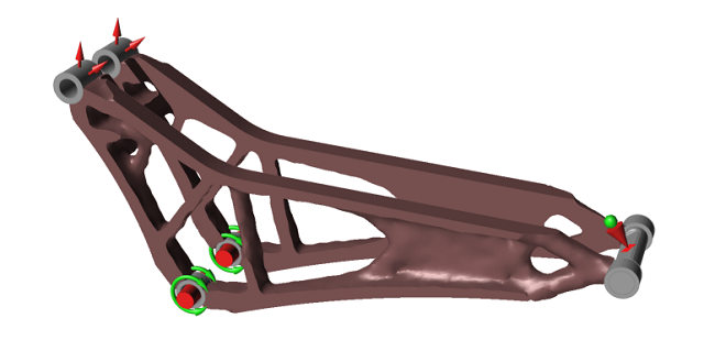
Drag the Topology slider on the Shape Explorer to
visualize the topology at different density thresholds. Every optimisation is
different, but a general guideline is to select a slider position where there
are no small holes in the topology and all significant members are
connected.
Figure 1. Example 1 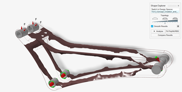
Figure 2. Example 2 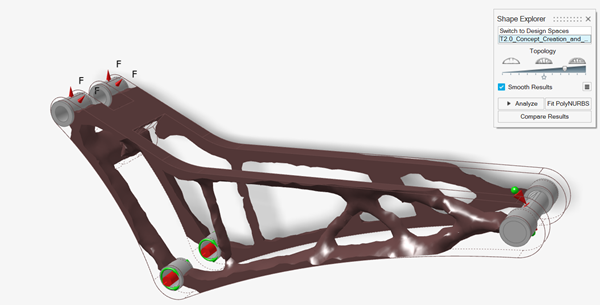
Figure 3. Example 3 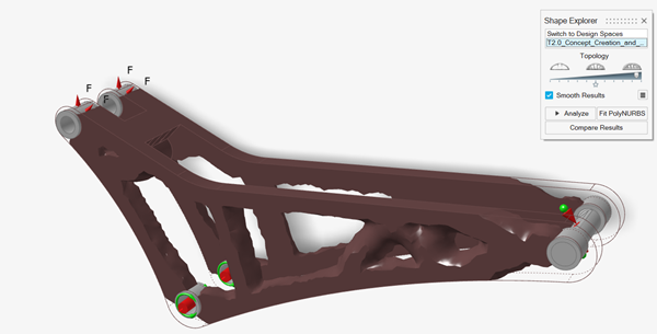
Analyze Topology Results
Use the Analyze button in the Shape Explorer to automatically generate and solve a finite element model based on the topology result shown and the original load cases. This reanalysis gives a quick indication of part performance indicating whether a topology concept is feasible.
-
Drag the Topology slider to the first tick from the
right.
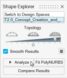
- Click Analyze.
-
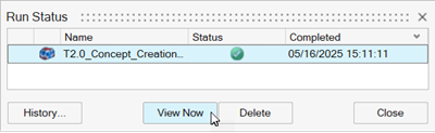
When the run is complete, select it in the Run Status window and click
View Now to view the results.
-
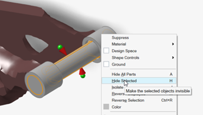
Hide the pin.
-
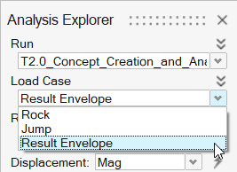
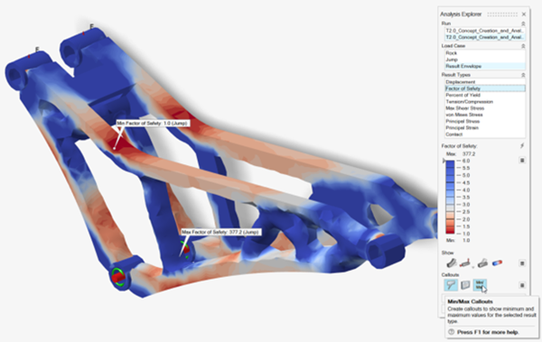
In the Analysis Explorer, select Result Envelope from
the Load Case dropdown.
-
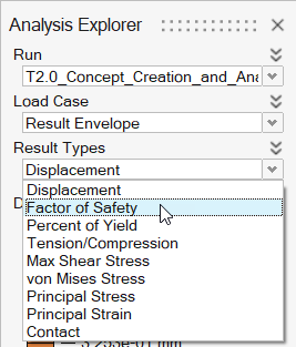
Select Factor of Safety from the Result
Types dropdown.
-
Turn on Min/Max Callouts to find the highest stress and
the load case where it occurs.
Automatically Building PolyNURBS Geometry
The Fit PolyNURBS function uses a multistage process to automatically build PolyNURBS geometry on topology optimization results.
-
In the Shape Explorer, click Smooth Results.
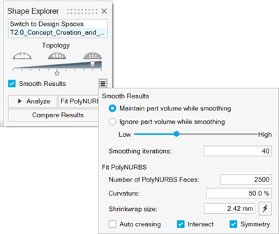
Smooth Results provides control parameters to adjust the results of the fit. Start with these control values and adjust as needed.Tip: For full control of the fitting process, you can use the following individual tools iteratively for more refined geometry:- On the PolyMesh ribbon, select the Shrinkwrap
tool
 and select the design and nondesign parts to wrap them in a
single isosurface.
and select the design and nondesign parts to wrap them in a
single isosurface. - On the PolyMesh ribbon, select the Smooth
tool
 and smooth the wrapped parts.
 - On the PolyNURBS ribbom, select the Fit tool
 to fit PolyNURBS to the smoothed wrap.
Tip: To find and open a tool, press Ctrl+F. For more information, see Find and Search for Tools. - On the PolyMesh ribbon, select the Shrinkwrap
tool
- Adjust the control values as needed.
-
Select the Intersect checkbox to apply a boolean
intersection between the created geometry and the original design space.
Intersect creates a ready-to-rerun model with no violations of the original design space, but can result in sharp features. When Intersect is not selected, the original PolyNURBS geometry is preserved, overlapping the nondesign regions. Some subsequent editing will be required for a run-ready model.
Fitting PolyNURBS to Topology Optimization
-
Double-click the
2.1_Analyze_Design_Concept_ReAnalysis.stmod file to
load it in the modeling window.
-
On the Structure ribbon, click the Show Optimization
Results button in the Optimize tool group
to view the Shape Explorer for the optimization that was previously run and
saved with the model.
This loads the topology optimization and opens the Shape Explorer. - Drag the Topology slider to the first tick from the right.
-
Select Smooth Results
 and examine
the parameters to be used in the wrap and fit process.
and examine
the parameters to be used in the wrap and fit process.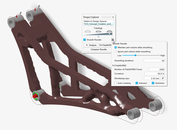
-
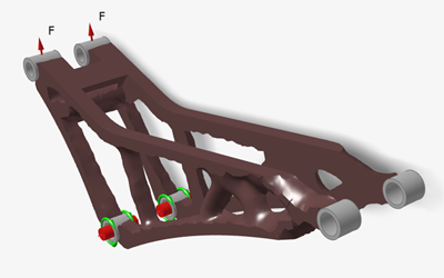
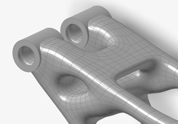
In the Shape Explorer, click Fit PolyNURBS.
The following geometry is created.
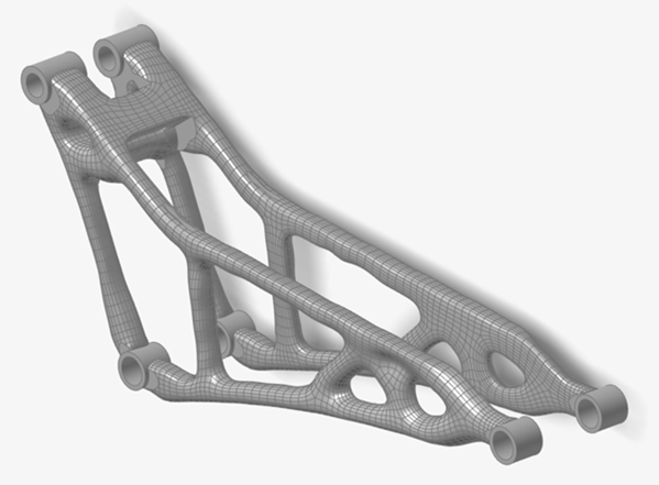 Note: Notice the flat features where the PolyNURBS geometry has been intersected with the original design space. Also notice that some of the members are slightly irregular. This is partly due to having a large number of PolyNURBS faces for the geometry detail and a relatively high curvature. This results in the fit closely following the details of the topology result. Smoother geometry can often be achieved by reducing these parameters, essentially smoothing over the smaller details.
 -
On the Structure ribbon, select the Contacts tool.

Tip: To find and open a tool, press Ctrl+F. For more information, see Find and Search for Tools.Bonded contacts have been created between the concept geometry and the original nondesign geometry.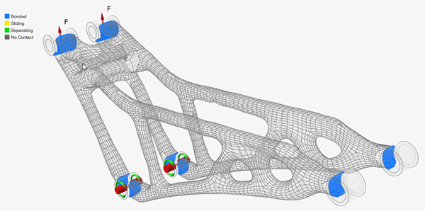
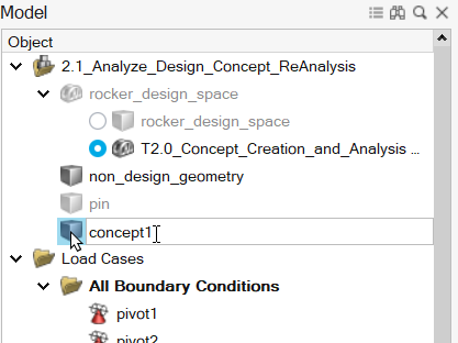
-
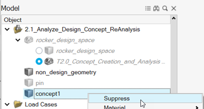
In the Model Browser, rename the generated part to
concept1.
-
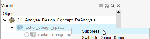
In the Model Browser, right-click the design space and select
Suppress.
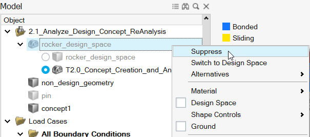
Suppressed parts are displayed in greyed-out, italicized text in the Model Browser. Suppressing a part prevents it from being included in analysis. All the original loads and supports are retained in the model as they were applied to the nondesign space. -
On the Structure ribbon, click the Run Analysis
 button in the Analyze tool
group.
button in the Analyze tool
group.

-
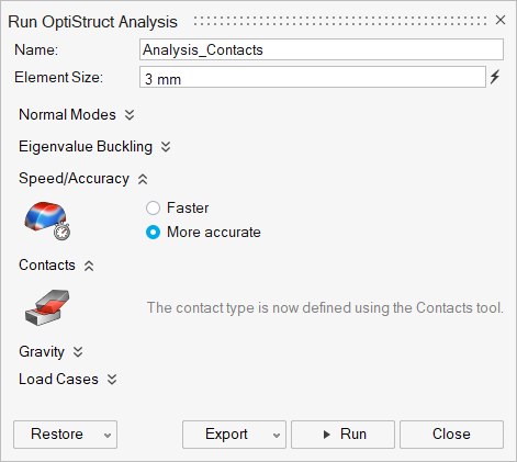
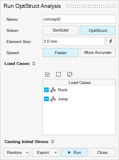
Run the analysis using the following settings.
- Rename the run concept1.
- Select OptiStruct as the solver.
- Change the Element Size to 3.0 mm.
- Set Speed to Faster.
- Click Run.
-
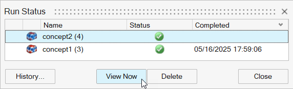
When the run is complete, select it in the Run Status window and click
View Now to view the results.

Tip: You can also double-click the Results icon in the Model Browser to view results for a load case.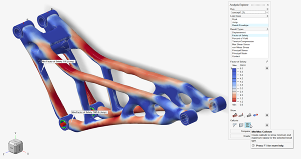
Refining PolyNURBS Fit
-
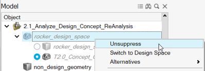
In the Model Browser, right-click concept1 and select
Suppress.
-
In the Model Browser, right-click rocker_design_space
and select Unsuppress.
-
On the Structure ribbon, click the Show Optimization
Results button in the Optimize tool group
to load the previous topology optimization in the Shape Explorer.
-
Select Smooth Results
and adjust the
smooth and fit parameters as shown:
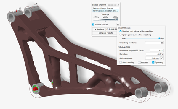
- Enter 80 in the Smoothing iterations box.
- Enter 1200 in the Number of PolyNURBS Faces box.
- Enter 40% in the Curvature box.
- Enter 2.42 in the Shrinkwrap size.
- Clear the Intersect checkbox.
-
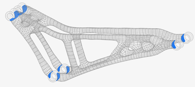
Select Fit PolyNURBS.
Notice that the resulting fit has fewer faces, no sharp features from the Boolean intersection and overlaps the nondesign geometry.
 Note: You can experiment with different fit parameters to see how the resultant geometry changes.
 -
In the Model Browser, right-click rocker_design_space
and select Suppress.
-
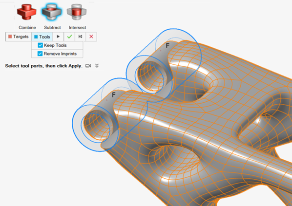
Separate the PolyNURBS geometry from the nondesign geometry.
-
On the Geometry ribbon, select the tool.

Tip: To find and open a tool, press Ctrl+F. For more information, see Find and Search for Tools. -
A guidebar appears with Targets automatically selected. Select the PolyNURBS geometry as the
target.
-
On the Geometry ribbon, select the tool.
-
Right-click the part, select Isolate, and then select
Convert Bodies to Parts.
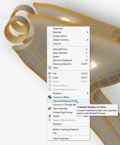
The PolyNURBS is converted into multiple separate parts as seen in the Model Browser.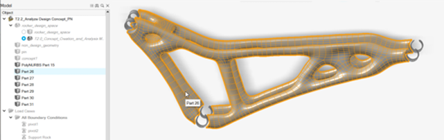
-
Identify the main part of geometry to keep, right-click it and rename to
concept2.
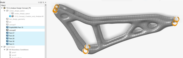
-
Delete the remaining originally overlapping parts.
As with the fully automated approach, the PolyNURBS geometry now perfectly contacts the nondesign geometry.
-
On the Structure ribbon, click the Run Analysis
button in the
Analyze tool group.
-
Run the analysis using the following settings.
- Rename the run concept2.
- Select OptiStruct as the solver.
- Change the Element Size to 3.0 mm.
- Set Speed to Faster.
- Click Run.
-
When the run is complete, select it in the Run Status window and click
View Now to view the results.
Tip: You can also double-click the Results icon in the Model Browser to view results for a load case. -
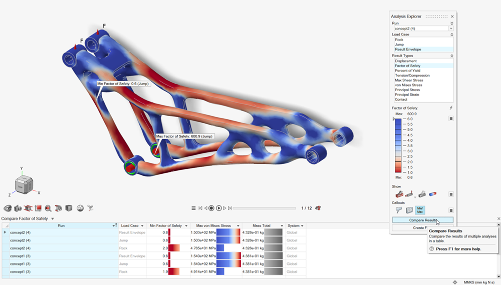
Click Compare Results to explore the differences between
design concepts.
Detail Concept Geometry
The final step in this tutorial is to detail the connection between the nondesign geometry and the concept geometry. In this example, combining the parts and detailing the connection completes the concept.
- Double-click the 2.2_Analyze_Design_Concept_PN.stmod file to load it in the modeling window.
-
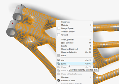
Right-click concept2 and select
Copy.
-
Right-click the model and select Paste without
reference.
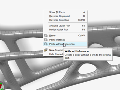
- In the Model Browser, right-click concept2 Copy, select Rename, and rename the copy to concept3.
- In the Model Browser, right-click concept2 and select Suppress.
-
Combine the continuous geometry from concept3 with the
nondesign geometry.
-
On the Geometry ribbon,
select the tool.
Tip: To find and open a tool, press Ctrl+F. For more information, see Find and Search for Tools. -
A guidebar appears with Targets automatically selected. Select
concept3 as the target.
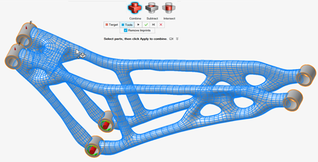
Tip: Choosing concept3 as the Target means the resulting part will retain its name and properties.
-
On the Geometry ribbon,
select the tool.
- In the Model Browser, verify that all parts except the pin and concept3 are suppressed.
-
On the Structure ribbon, click the Run Analysis
button in the
Analyze tool group.
-
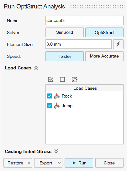
Run the analysis using the following settings.
- Rename the run concept3.
- Select OptiStruct as the solver.
- Change the Element Size to 3.0 mm.
- Set Speed to Faster.
- Click Run.
-
When the run is complete, select it in the Run Status window and click
View Now to view the results.
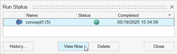
Tip: You can also double-click the Results icon in the Model Browser to view results for a load case.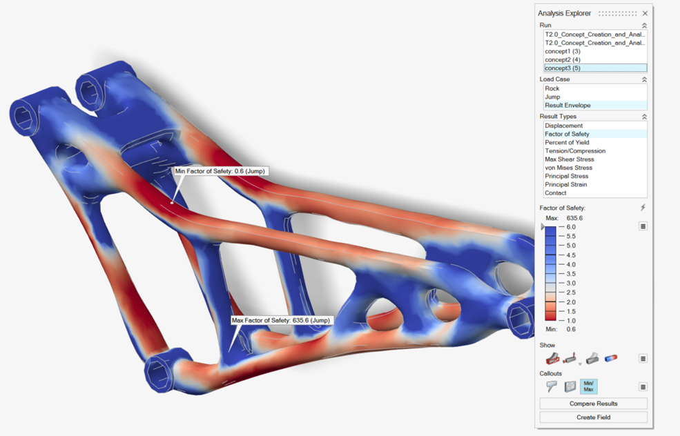
-
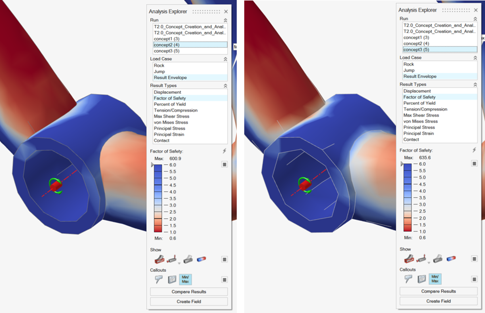
In the Analysis Explorer, select concept2 and
concept3 from the Run dropdown
and compare the results.
Notice that by combining the parts created stress continuity at the connections.
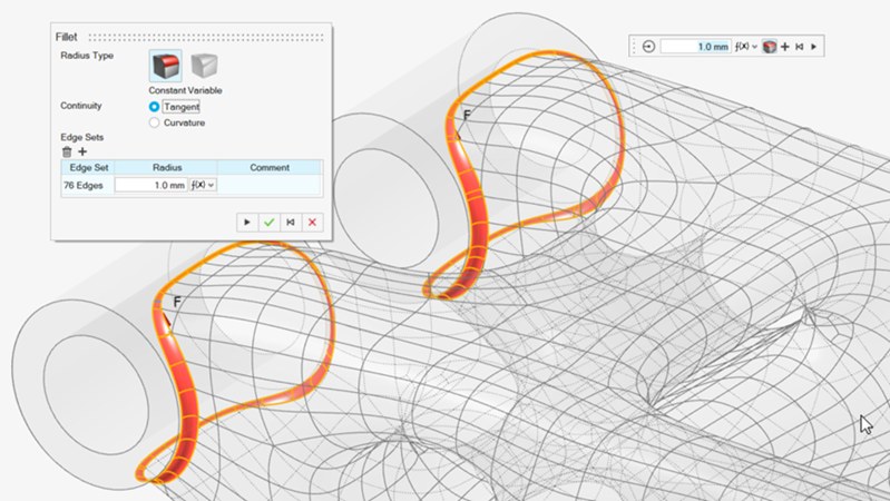
-
If desired, you can use the Fillet tool to detail the
geometry and run another analysis as concept4.