Minimizing mass is one of several optimization objectives, and is available with
topology, and gauge optimization.
Minimizing Mass for Topology Optimization
When running a topology optimization, minimizing the mass of a design space will
result in a shape that is the lightest weight possible that can still support the
applied loads. If you select Minimize Mass as your
optimization objective, you will need to specify one or more of the following:
Stress Constraints - applied using the
Run Optimization window and specified in terms of
a safety factor.
Frequency Constraints - applied using the
Run Optimization window.
Displacement Constraints - applied using the
Displacement Constraints tool.
Note: Once
optimization is complete, the best result when minimizing mass is
generally found by dragging the topology slider to the far right in the
Shape Explorer.
Minimizing Mass for Gauge Optimization
When running a gauge optimization, minimizing the mass of a design space will change
the thickness of the part to minimize mass. If you select Minimize
Mass as your optimization objective, you will need to specify one or
more of the following.
Stress Constraints - applied using the
Run Optimization window and specified in terms of
a safety factor.
Displacement Constraints - applied using the
Displacement Constraints tool.
Frequency Constraints - applied using the
Run Optimization window.
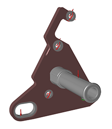
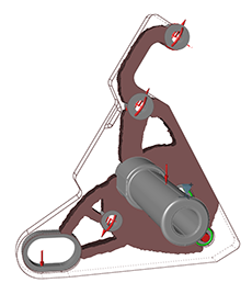
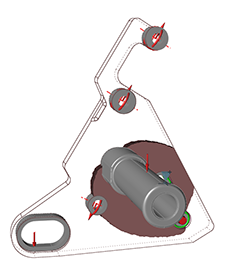
Example 1: Minimizing Mass Subject to Stress Constraints
The motorcycle bracket pictured below was optimized by minimizing mass subject to
stress constraints, defined in terms of a minimum safety factor. As the safety
factor increases, more material to resist the loads you've applied.Figure 1. Original Model Figure 2. Stress Constraint with a Safety Factor of 1.2Figure 3. Stress Constraint with a Safety Factor of 2.0
Example 2: Minimizing Mass Subject to Stress and Displacement Constraints
A displacement constraint can be applied to restrict a certain point on your model
from deflecting more than a specified distance from its original location. In the
example images below, a displacement constraint has been applied to the foot peg of
the motorcycle bracket in addition to a stress constraint. As the allowable
displacement at the peg decreases, the optimized shape requires more material to
resist the deflection.Figure 4. Displacement Constraint of 2 mm at the Foot Peg Figure 5. Displacement Constraint of 1 mm at the Foot Peg
Note: When using displacement constraints, we recommend applying stress
constraints as well. If used alone, displacement constraints can bias the
optimization, resulting in disconnected areas, as shown in the first image
below:
Figure 6. Displacement Constraint of 2 mm at the Foot Peg with No Stress
Constraint
Figure 7. Displacement Constraint of 2 mm at the Foot Peg with a Stress
Constraint