Maximize Stiffness
Maximizing stiffness is one of several optimization objectives, and is available with topology, topography, and gauge optimization.
Maximizing Stiffness for Topology Optimization
- Mass Targets - Recommended; applied using the Run Optimization window.
- Frequency Constraints - Optional: applied using the Run Optimization window.
- Displacement Constraints - Optional; applied using the
Displacement Constraints tool.Note: Once optimization is complete, the best result when maximizing stiffness is generally found in the middle of the topology slider near the star in the Shape Explorer. The optimal result is the point at which all of the load and support locations are connected.
Maximizing Stiffness for Topography Optimization
- Bead Options - applied using the Run Optimization window.
- Displacement constraints - applied using the Displacement Constraints tool.
- Frequency constraints - applied using the Run Optimization window.
Maximizing Stiffness for Gauge Optimization
- Total Mass Target - applied using the Run Optimization window.
- Displacement Constraints - applied using the Displacement Constraints tool.
- Frequency Constraints - applied using the Run Optimization window.
Example: Maximizing Stiffness Subject to Mass Targets
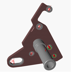
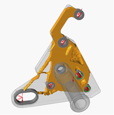
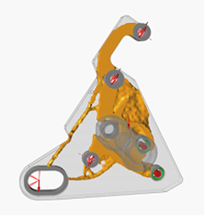
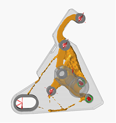
The motorcycle bracket pictured below was optimized by maximizing stiffness using several different mass targets.
With a mass target of 50% of the total design space, the result is fully connected. The next step is to try decreasing the mass target to see if you can achieve a similarly connected part.


This means the resulting shape's load path is not well-defined. Comparing the three results, the one with the mass target of 30% would be the best starting point for your design, as it provides the lowest mass that connects al off the support and force locations.