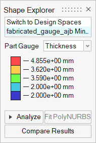
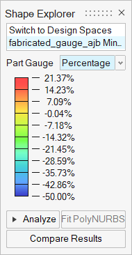
Gauge Optimization
Gauge optimization is used to optimize the thickness of a design space. Note that gauge optimization only works on parts that are defined by surface geometry.
Use the Run Optimization tool to set up and run a gauge optimization.
- Gauge optimization can be run on its own or concurrently with topography optimization.
- Gauge thickness targets for each design space are defined in the Run Optimization window.
- When optimizing the gauge, you can maximize stiffness, maximize frequency, or minimize mass as your optimization objective. When maximizing stiffness, a target mass is required and it is advisable to use a displacement constraint. When minimizing mass, it is best to use a stress constraint.
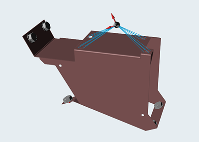
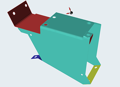
Target Mass
A target mass is required when your objective is to maximize stiffness. This is the total target mass of the model after optimization, which is achieved by optimizing the gauge thickness of each individual part in the assembly. The target mass defaults to the total mass of the parts before optimization.
Element Size
The element size dictates the quality of your results. In general, the smaller the element size, the more accurate the result, but the slower it will run.
Click the ![]() icon to revert to the default value.
icon to revert to the default value.
Gauge Thickness
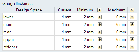
The current gauge thickness for each design space is displayed in the Run Optimization window, and can be defined there or in the Property Editor.
The target Minimum and Maximum gauge thickness are defined by the user, and default to 20% above or below current gauge thickness.
Shape Explorer for Gauge Optimization
