Displacement constraints can be applied to a model to limit deflections in desired
locations and directions.
You can choose to limit displacement in one direction or in all directions, as shown
in the images below. A displacement constraint in one direction can have an upper
bound, lower bound, or both.
Displacement Constraint in One Direction with an Upper and a Lower Bound Displacement Constraint in All Directions
Apply a Displacement Constraint in All Directions
On the Structure ribbon, select the Displacement
Constraints tool.
Move your mouse over a non-design space in the modeling window and click on a
point.
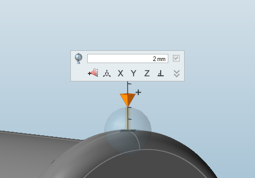
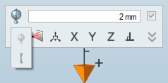
Click on the sphere in the microdialog to modify the type of displacement
constraint.
A displacement constraint in all directions, represented as a sphere, is
created where you click.
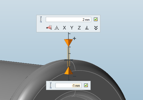
Click on the Constrain in One Direction icon in the
drop-down list to apply the displacement constraint in a single direction.
Two orange pyramids appear, each with a separate microdialog, to
represent the upper and lower bounds for the displacement
constraint.
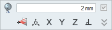
Click and drag an orange pyramid, or click the button and enter a
value in the text fields of the microdialog, to change the magnitude of the
upper or lower bound for the displacement constraint.
If you only want an upper or lower bound, not both, turn off the checkbox in
the microdialog for the bound you want to remove.
To change the direction of the displacement constraint:
Click the X, Y, or
Z on the microdialog.
Click the Move tool icon on
the microdialog, then click and drag the arrows or enter a precise value in
the text box.
Click the
button and manually enter the x, y, and z components of the direction
vector.
Press the button to revert to the default
direction.
Right-click and mouse through the check mark to exit, or double-right-click.
Tip:
Displacement constraints should only be applied to non-design spaces.
While they can be used as the sole constraint for an optimization, we
recommend using displacement constraints alongside a stress constraint.
Use the right-click context menu to include or exclude a displacement
constraint from a load case.
Microdialog Options
Double-click on a displacement constraint to enter editing mode, which opens a
microdialog.
Apply the displacement constraint in one direction or all directions.
Enter a magnitude or upper and/or lower bound for the displacement constraint.
When applying in one direction, use the check boxes to define whether to use a lower
and/or upper bound.
Click the icon to enter/exit Multi-Selection mode. In this mode, you can click a
feature to add/remove it from the selection. Outside of this mode, you need to hold
down Ctrl while clicking.
Translate or rotate the displacement constraint using the Move tool.
Align the displacement constraint to an axis or normal to the face.
Click to orient the displacement constraint by entering component vectors for x,
y, and z. (For example, entering 1, 0, 0 would orient it in the positive x
direction.)
FAQs: Displacement Constraints
Find answers to frequently asked questions about displacement constraints.
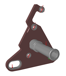
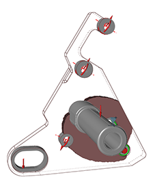
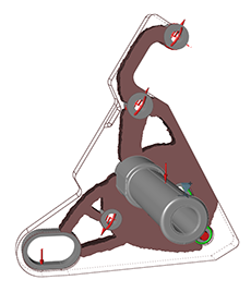
Why Are My Results Disconnected?
When you use displacement constraints, it is important to either apply them near all of the
major loads or to use both stress constraints and displacement constraints together.
As shown in the first two images below, if you apply a single displacement constraint of 2
mm at the tip of the foot peg, the results are biased to only account for that displacement
constraint. The third image shows how the optimized result changes if a stress constraint
with a factor of safety of 1.2 is added to the displacement constraint. The resulting shape
can resist the stress applied while maintaining a total displacement of 2 mm at the foot
peg.Figure 1. Original Model Figure 2. Displacement constraint of 2 mm at the foot peg with no stress constraint Figure 3. Displacement constraint of 2 mm at the foot peg with a stress constraint


 button and enter a
value in the text fields of the microdialog, to change the magnitude of the
upper or lower bound for the displacement constraint.
button and enter a
value in the text fields of the microdialog, to change the magnitude of the
upper or lower bound for the displacement constraint.
 on
the microdialog, then click and drag the arrows or enter a precise value in
the text box.
on
the microdialog, then click and drag the arrows or enter a precise value in
the text box. button to revert to the default
direction.
button to revert to the default
direction.