
View Flexible Parts as a Table
On the main ribbon, select the List Table satellite icon  in the FlexBody tool group to open the table.
Tip: To find and open a tool, press
Ctrl+F. For more information,
see Find and Search for Tools.
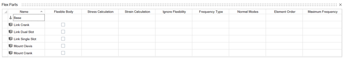
The flex body table appears. It contains an organized layout of the parameters
associated with flex bodies:
Note: For options to appear in
the Flex Part columns, the corresponding part must be a flexible body.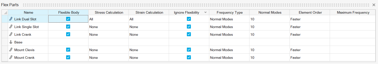 To make a part a flexible, enable the switch in
the Flexible Body column in the Flex Parts table. You
can also right-click the part in the modeling window, then enable
Flexible for Motion.
To make a part a flexible, enable the switch in
the Flexible Body column in the Flex Parts table. You
can also right-click the part in the modeling window, then enable
Flexible for Motion.
To make a part a flexible, enable the switch in
the Flexible Body column in the Flex Parts table. You
can also right-click the part in the modeling window, then enable
Flexible for Motion.The parameter functions are listed in the table below:
| Flex Parts Parameter Category Name | Function | Notes |
|---|---|---|
| Name | Shows the name of the part in the model. | Hovering over the part name in the table highlights the corresponding part in the model. |
| Flexible Body | Contains the switch to make a part in the model Flexible for motion. | You can also right-click the part in the modeling window, then enable Flexible for Motion. |
| Stress Calculation | Shows the stress results of the flexible body motion analysis. | |
| Strain Calculation | Shows the strain results of the flexible body motion analysis | |
| Ignore Flexibility | Enable this option to consider the flexible body as rigid, but use the mass and inertia properties generated from the flexible body data. | |
| Frequency Type | Depending on which Frequency Type you select, the calculated modes of the flexible body will be based on a Maximum Frequency cutoff value, or a specific number of Normal Modes. | |
| Normal Modes | Enter a value for the Number of Modes (not including rigid body modes) to include in the flex body definition. | |
| Element Order | Choose the element representation level: Faster (1st order) or More accurate (2nd order). | |
| Maximum Frequency | Shows the maximum flexible body mode frequency to use in the flexible body definition. |
| To | Do this |
|---|---|
| Multi-select table parameters | Use Ctrl+Select or Shift+Select while in the Flex Parts table context. |