
Connection Radius
Connection Radius:
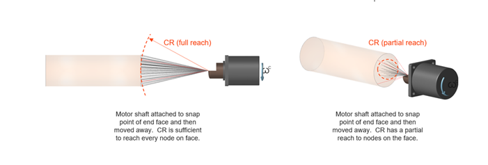
When modeling with flexible bodies, certain entities such as springs, motors, and actuators must be sufficiently attached to the flex body to transmit forces. The Connection Radius (CR) parameter associated with these entities is the minimum (spherical) reach-out radius that originates from one of the entity's definition points. The purpose of the CR is to ensure that the entity can reach nodes on the flex body for sufficient attachment. In finite element terminology, the actual connection used between the entity and flex body is RBE2.
Here are some examples of how the connection radius is revealed on the part, as seen in the Flex Modes review:


How Is the Connection Radius Determined?
The Connection Radius (CR) is automatically calculated when entities such as springs, motors, and actuators are first created. Initially, it is directly associated with the entity graphic sizing that you can adjust if you double-click the motor or actuator and drag the handle. For example, the initial CR value of a motor is equal to the motor shaft's radius, and the initial CR value of a spring-damper is equal to half the spring's diameter. If the CR is overridden automatically by the simulation or by the user, the CR value will no longer be associated with the graphic size.
When Does the Connection Radius Get Overridden?
- Use the Flex Body Modes review to visualize and verify that the connectors for entities are properly attached to the flex body.
- Be sure to turn off the override option each time the flex body mesh element size is changed. That way, the CR will automatically determine a new value based on the new mesh size and ensure attachment. Otherwise, it is your responsibility to monitor that the CR is sufficient.
- It is possible for the flex body to be created with an insufficient CR.
If this happens, when the analysis is run, an error message will appear
and guide you to the web help to resolve it.
