
Flexible Body Contact
Two methods are available for enhancing the behavior of flexible bodies: FlexContact+ and FlexContact+ for Joints. Both methods involve a form of geometry-based contact to improve flex body results accuracy, capturing realistic behavior of contact area stress/strain and stress/strain near joint locations.
When Should I Use FlexContact+ vs. FlexContact+ for Joints?
FlexContact+
If there is a general contact defined on a flex body, such as with a pin in a slot, FlexContact+ can be used to improve flex body behavior to account for stress/strain at the contact interface due to contact loads.
FlexContact+ for Joints
If modeling flex bodies that have non-pin joint connections, such as a cylinder in a hole, the FlexContact+ for Joints option can be used to capture more detailed representations of stress/strain at the joint.
Hybrid Approach
A model can also use a hybrid approach where both methods are applied to one or more flexible parts. This can be useful when flexible parts have both free-behaving contacts as well as geometry-based joints associated with them; for example, a cam-follower. The cam and follower might have joints at their pivoting centers, but there is also a general contact where the two parts interact. If performing a flex analysis of either the cam or the follower, a hybrid approach could be used.
FlexContact+
When using flexible bodies in a motion contact, consider stress or strain at the contact interface by performing a more comprehensive and predictive analysis. You can model contacts between rigid/flexible and flexible/flexible parts.
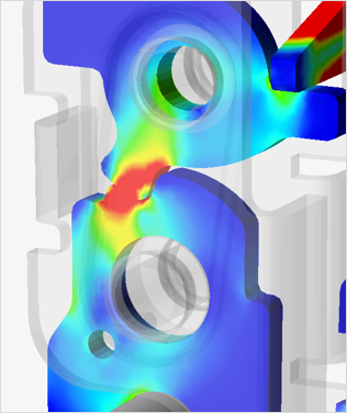
FlexContact+ uses a unique process to also account for flex body deformation involving loads generated from general part-to-part contact. This method is useful for when there is at least one motion contact between a flexible part and another rigid or flexible part, and it is desired to capture a higher result accuracy of stress/strain at the contact interface. This process extends the traditional CMS (Component Mode Synthesis) process by also considering additional flex body mode shapes based on the contact region and behavior. In the end, an enhanced version of the CMS flex body is generated that is an aggregate consideration of all these modes.
- First, create a flexible body.
-
Hover over the Analyze Motion tool and click the
Run Settings
 satellite icon.
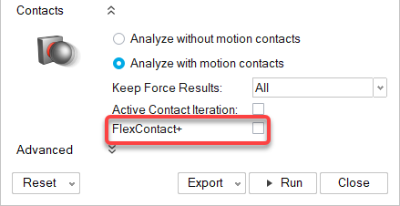
- Under Contacts, turn on FlexContact+.
- Select the Run button.
FlexContact+ for Joints
Account for flex body deformation involving loads occurring around the joint region. This method is useful for when there is a joint connected to the flex body that is defined by geometric features, and it is desired to capture a higher result accuracy of stress/strain at the part regions near the joint.
This process takes the same information that would be used in a traditional CMS (Component Mode Synthesis), but rather than use spider connections for joints between flexible parts and other parts, the spiders are removed, and additional flex body modes are calculated which account for the joint loading. The result is a flex body that accounts for realistic stress/strain due to deformation around the joint.
- The joint cannot be a Pin joint type.
- The geometry located at the joint must be representative of the true physical joint such that, if the joint was replaced with a part-to-part contact, the joint would behave with its intended degrees of freedom.
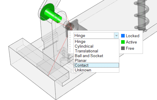
The Contact joint behaves like a regular motion contact. It is geometry contacting geometry. A Contact joint uses the same parameters for controlling the behavior of the contact (stiffness, damping, penetration and exponent). Avoid interfering and/or touching (coincident) geometry. Use the Inspire Geometry tools to modify geometry where and when possible.

-
Double-click a joint and change the type to
Contact.
- Verify that the geometry at the joint interface is clean of interferences and has the proper geometric clearances included (if possible, avoid 0 clearance fits).
-
Hover over the Analyze Motion tool and click the
Run Settings
satellite icon.
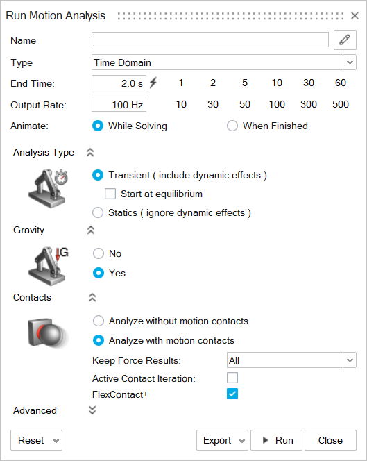
- Under Contacts, turn on FlexContact+.
- Select the Run button.