Run Analysis on a Part
Use the Run Part Analysis tool to define and run a linear static, normal modes, or buckling modes analysis on a motion part.
-
Click Run Analysis
 on the Analyze Part
icon.
 Tip: To find and open a tool, press Ctrl+F. For more information, see Find and Search for Tools.
 -
Select a part to analyze. The Run Part Analysis window
appears.

- The Name defaults to the name of the part, but you can enter an alternate name in the text entry field.
- Change the Element size if desired. Increase the value to obtain coarser results; decrease the value to obtain finer results.
- Optional:
If you want to analyze Normal modes, click the
 button
and choose the number of modes to include. You may also select whether to
include supports from a particular load case in the drop-down menu.
- Under Speed/Accuracy, select Faster or More accurate.
- Define which method to use when extracting the Loads from Motion.
- If at any time you want to restore the default options for the Run Part Analysis window, click Restore and select Defaults.
- Click the Run button to start the analysis.
Tip:
- If you select a part that is a member of a rigid group, the whole rigid group will be analyzed.
- If you don't want to wait for the run to finish, you can close the Run Status window and continue working in Inspire. You can check on the status of a run at any time by clicking the Run Status tool on the Analyze Part icon.
- There is no design space for an analysis, so there is no requirement to break up your model into design and non-design spaces and apply loads only to the latter. Any part can be analyzed. However, if you intend to optimize the part later, it is beneficial to split your part into design and non-design spaces and apply appropriate loads and supports prior to running a baseline analysis.
- If you want to run reanalysis on an optimized shape, double-click it, then use the Analyze button on the Shape Explorer.
- For more accurate results, you should run optimization with the Accurate option selected. Then the reanalysis will utilize the 2nd order elements (for more accuracy).
Export a FEM File
-
Click Run Analysis
 on the Analyze Part icon.
The Run Analysis window appears.

Tip: To find and open a tool, press Ctrl+F. For more information, see Find and Search for Tools. - Click the Export button on the Run Analysis window and select a unit system for export..
- Choose a directory and a name for your file, then click Save.
- When the export is complete, double-click the name of the run to open the directory where the FEM file is located.
Loads from Motion
The options on the Run Analysis window are the same as when running an analysis using the Analyze tool on the Structures ribbon, except the Load Cases section is replaced with Loads from Motion.
Loads from Motion
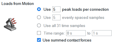
When you analyze a part using a motion run, the part is loaded from the results of the motion simulation. You can choose to select which points in time are analyzed by extracting the peak loads, evenly spaced time samples, all time samples, or range of times.

- Use # peak loads per connection: This option will extract time samples where peak loads occurred during the previously run motion analysis. This is the default option.
- Use # evenly spaced samples: This option will extract evenly spaced time samples from the previously run motion analysis. This is useful for seeing how stresses develop as the part is moved.
- Use all # time samples: This option will extract loads from all time samples from the previously run motion analysis.
- Time range # to #: Select the checkbox to define a time window to limit the number of samples. This can be applied to any of the three options above.
- Use summed contact forces: This option will use a Summed at Contact Region representation of the contact forces instead of the individual contact forces themselves.
Note: The number of load cases in the Analysis Explorer can differ from what was requested
when using the peak loads option. When extracting peak loads, Inspire checks in the global
x, y, and z directions for forces and torques in every connection on the part. So
sometimes you will get more load cases than peak loads requested. On the other hand, if
the peak loads occur at the same time, it reduces the number of load cases.