Use the Force Explorer tool to visualize force and torque vectors in a motion
analysis.
This tool can be accessed by clicking the Force Explorer tool on
the Motion ribbon.
Location: Motion ribbon, Review group
The visualization is available for joints,
motors, motion contacts, and other entities during the run or when playing back the
results. This is useful for understanding how loads are developing in your mechanisms,
as well as presentations and debugging.
Show Options
The show options let you control the visibility of each entity. The Force Explorer
does not draw vectors for entities that have been hidden in the Model Browser.
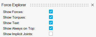
Figure 1. Force Explorer
Show Forces
Show or hide all forces in the motion run.
Show Torques
Show or hide all torques in the motion run.
Show Text
Show or hide the numerical values associated with the forces and torques.
Motion contacts do not show a numerical value unless you have selected the
Sum Forces option under Contact Forces.
Show Always on Top
Always show the force or torque vectors drawn on top of the geometry.
Show Implicit Joints
Show or hide all forces and torque vectors associated with implicit
joints.
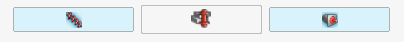
Use the entity buttons to toggle the visibility force/torques associated
with specific motion entities. The number of buttons changes based on what
types of motion entities are in the model; they can be toggled while the
analysis is being run.
Tip:
Keep in mind that showing a large number of vectors and text can slow
down the animation playback speed. We recommend toggling off information
you don't need to visualize.
The entity button for joints is toggled off by default to minimize the
number of vectors drawn.
Force/torque vectors are not drawn for motors or actuators with a
Controller Type of Soft Constraint.
When reviewing motion results, force and torque vectors can be selected
for plotting.
You can dock and undock the Force Explorer.
Contact Forces
The Contact Forces section allows you to control the visibility of motion contact
forces.
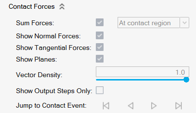
Figure 2. Contact Forces
Sum Forces
This option converts several force vectors into an equivalent force/torque
combination. When unchecked, the numerical value is not reported.
At contact region (default): A minimal set of
arrows is used to convey contact occurring at different regions of
the part.
At center of gravity: A force and torque
arrow pair is drawn at the center of gravity of the part(s) in
contact.
Show Normal Forces
Show or hide the contact normal force component.
Show Tangential Forces
Show or hide the contact friction force component.
Show Planes
Show or hide the planes drawn at the base of the normal vector arrow.
Vector Density
Use the slider to reduce the number of vectors drawn for the contact region.
A value of 1 shows all of the vectors, while a value of 0 shows one.
Show Output Steps Only
Motion contact results typically have intermediate frames interspersed
between the output steps for contact visualization. You can use this option
to suppress the intermediate frames and show only the output steps. This is
helpful when you want uniform time spacing between your playback output
frames.
Jump to Contact Event
When animation playback is paused, you can jump to the first, previous,
next, or last contact event. If you hold down the Previous or Next button,
it will auto-repeat.
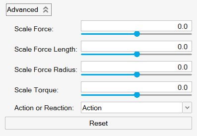
Advanced Options
The Advanced options allow you to scale motion contact forces and torques and define
whether to show action or reaction forces.
Figure 3. Advanced Options
Scale Force
Drag the slider to scale the force vector relative to the model.
Scale Force Length
Drag the slider to change the length of force vectors.
Scale Force Radius
Drag the slider to change the radius of force vectors.
Scale Torque
Drag the slider to scale the torque vector relative to the model.
Action or Reaction
Select whether to show action forces, reaction forces, or both.