
Tracers
Use the Tracers tools to visualize the path of a trace part or trace point during a motion run.
After a path is drawn, it can be used for geometry creation and modification. You can synthesize shapes (like cams) from the part's motion by choosing to draw the path on a moving reference frame.
Click the satellite ![]() icon that appears when you hover over the Tracers tool to
view a list of all tracers in your model.
icon that appears when you hover over the Tracers tool to
view a list of all tracers in your model.
Trace a Part
Visualize the trace of a part and perform geometry operations after a motion run.
-
Select the Trace Part tool.

Tip: To find and open a tool, press Ctrl+F. For more information, see Find and Search for Tools. - Optional: On the guide bar, select the hamburger menu to preconfigure the settings for creating the trace and performing geometry operations. For more information, see Step 5.
-
Select a part to trace.
The part will be drawn in the reference frame of the reference part.
-
Select a reference part. Select the same part twice to use ground.
The trace will be generated from the viewpoint of the reference part. If the trace and reference parts are different, the Boolean operations tool will be available to combine, subtract, or intersect them.
-
Configure the settings for creating the trace and performing geometry
operations.
Options Description Frames Specify the number of frames from the motion simulation to use for the trace. Use all frames or specify a specific range.
- Use all (x) samples: Preview
the trace using all time steps of the motion
analysis.Tip: For repeated motion, it might not be necessary to use all the frames, as there may be redundant frames included.
- Time Range: Preview the trace during a specific time range of the motion analysis.
Resolution Adjust the resolution of the trace preview.
- Voxel Size: Adjust the previewed part quality by adjusting the size of the voxel mesh used for the preview. A larger voxel size reduces part quality but improves preview performance, whereas a smaller voxel size increases part quality but performance may be slower.
- Interpolation: Adjust the previewed path quality by adjusting the interpolation between motion frames. A lower interpolation reduces the path quality but improves preview performance, whereas a higher interpolation increases path quality but performance may be slower.
Fit Set options for converting the preview into a PolyNURBS part.
- Number of PolyNURBS Faces: Specify the Number of PolyNURBS (cage) faces that will define the final trace part. Reducing this value will increase the size of the PolyNURBS cages but will capture less detail. In general, you want to use the fewest number of PolyNURBS faces that still captures the geometry. The default is 2500.
- Curvature: Specify the curvature of the PolyNURBS fit, as a percentage. Entering a higher percentage for the Curvature will capture more features. The default is 50%.
Result Use the PolyNURBS fit result and perform a geometry operation between the selected trace part and reference part.
- New Part (default): Create a new part using the trace preview.
- Combine: Combine the trace part with the reference part. Available only when using a non-ground reference.
- Subtract: Subtract the trace part from the reference part. Available only when using a non-ground reference.
- Intersect: Retain only the intersecting positions of the trace and reference parts. Available only when using a non-ground reference.
- Use all (x) samples: Preview
the trace using all time steps of the motion
analysis.
-
Click the Apply
 button.
- Right-click and mouse through the check mark to exit, or double-right-click.
Trace a Point
Visualize the trace of a point after a motion run.
-
Select the Trace Point tool.

Tip: To find and open a tool, press Ctrl+F. For more information, see Find and Search for Tools. -
Click on a part to place a trace point.
The trace point acts as the pen.
- Optional: Hold down the Ctrl key and select a reference part to act as the paper.
- Run the motion analysis, or if a run already exists, the trace path will appear.
- Optional: To see a partial trace path of the last ten frames during animation, select Enable Trail in the Property Editor. Adjust the trail Frames value to lengthen or shorten the trace path.
- Optional: To see a full trace path for the last valid motion run, enter a Tracers tool or use the Review Motion Results tool and view the last step in the animation.
- Right-click and mouse through the check mark to exit, or double-right-click.
- If you move tracers with the Move tool on the microdialog, the traced paths will update automatically.
- Tracers are associated with part features. The tracer may be deleted if changes are made to the part feature or geometry associated with it.
- Tracers can be hidden or shown by clicking their icons in the Model browser or by using the context menu.
- You can change the color and line thickness of the tracer and its trace path in the Property Editor.
- The Export Locations option in the context menu allows you to save a .csv file containing global x, y, z location data.
- You can Suppress/Unsuppress a tracer to understand its effect on your model. Right-click it and select Suppress. Right-click it from the Model Browser or Table and select Unsuppress.
Creating Geometry from a Trace Path
- Create a tracer and run a motion analysis.
- Right-click on the tracer and select Create Spline from the context menu. A massless part is created in the Model Browser. This part can now be pushed, pulled, and otherwise manipulated.
- To create valid splines, make sure the trace path does not loop back over itself. Try reducing the End Time to control how far the trace path extends.
- Alternatively, you can create a polyline by selecting Create Polyline from the context menu. Polylines are segmented rather than smooth line spline curves.
- Multiple selection is supported if you have multiple trace paths that you want to convert to splines or polylines.
- If you want to keep a tracer for future use, ground the spline that you created or add it to a rigid group.
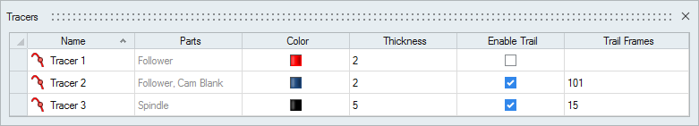
Tracers Table
The Tracers Table lists all of the tracers in your model and allows you to edit various attributes.
Location: Tracers tool, satellite icon ![]()
| To | Do this |
|---|---|
| Rename a tracer | Select the cell in the table and then click again to make the field editable. |
| Change the color | Select the color cell in the table and then select a different option from the color palette. |
| Sort a column | Click the column header. Click repeatedly to toggle between ascending and descending order. |
| Add or remove columns | Right-click on a column header. |
Shortcuts
| To | Do this |
|---|---|
| Select a reference part | While a tracer is selected, hold down the Ctrl key and left-click a part to act as the paper. |
| Exit the tool | Right-click and mouse through the check mark to exit, or double-right-click. |