
/PROP/TYPE22 (TSH_COMP)
Block Format Keyword This property set is used to define the composite thick shell property set.
Format
| (1) | (2) | (3) | (4) | (5) | (6) | (7) | (8) | (9) | (10) |
|---|---|---|---|---|---|---|---|---|---|
| /PROP/TYPE22/prop_ID/unit_ID or /PROP/TSH_COMP/prop_ID/unit_ID | |||||||||
| prop_title | |||||||||
| Isolid | Ismstr | Icstr | Inpts | Iint | dn | ||||
| qa | qb | ||||||||
| VX | VY | VZ | skew_ID | Iorth | Ipos | ||||
| Ashear | |||||||||
| (1) | (2) | (3) | (4) | (5) | (6) | (7) | (8) | (9) | (10) |
|---|---|---|---|---|---|---|---|---|---|
| ti/t | Zi | mat_IDi | |||||||
| (1) | (2) | (3) | (4) | (5) | (6) | (7) | (8) | (9) | (10) |
|---|---|---|---|---|---|---|---|---|---|
| Vdef_min | Vdef_max | APS_max | COL_min | ||||||
Definition
| Field | Contents | SI Unit Example |
|---|---|---|
| prop_ID | Property
identifier. (Integer, maximum 10 digits) |
|
| unit_ID | Unit Identifier. (Integer, maximum 10 digits) |
|
| prop_title | Property
title. (Character, maximum 100 characters) |
|
| Isolid | Solid elements formulation flag.
(Integer) |
|
| Ismstr | Small strain formulation
flag. 4
(Integer) |
|
| Icstr | Constant stress
formulation flag. Only valid for Isolid =
14.
(Integer) |
|
| Inpts | Number of integration
points. 2
(Integer) Where,
|
|
| Iint | Number of layers when 9
< number of layers ≤ 200. Only valid for Isolid =
14. 4 (Integer) |
|
| dn | Numerical damping for
stabilization. Only valid for Isolid =
15. Default = 0.1 (Real) |
|
| qa | Quadratic bulk
viscosity. Default = 1.10 (Real) Default = 0.0 for /MAT/LAW70 |
|
| qb | Linear bulk
viscosity. Default = 0.05 (Real) Default = 0.0 for /MAT/LAW70 |
|
| Ashear | Shear factor. Default = 1.0 (Real) |
|
| VX | X component for reference
vector. Default = 1.0 (Real) |
|
| VY | Y component for reference
vector. Default = 0.0 (Real) |
|
| VZ | Z component for reference
vector. Default = 0.0 (Real) |
|
| skew_ID | Skew identifier. If the local skew has been defined, its X-axis replaces the reference vector (VX, VY, and VZ will be ignored). (Integer) |
|
| Iorth | Orthotropic system
formulation flag for reference vector.
(Integer) |
|
| Ipos | Layer positioning flag for
reference vector.
(Integer) |
|
| Angle for layer
I. (Real) |
||
| ti/t | Relative thickness of
layer i.
(Real) |
|
| Zi | Z position (normalized by
the thickness) of layer i (-0.5 ≤
Zi ≤
0.5). Default = 0.0 (Real) |
|
| mat_IDi | Material identifier for
layer I. (Integer) |
|
| Minimum time
step. Default = 106 (Real) |
||
| Vdef_min | Minimum volume ratio
(V/Vo) to delete solid element. Default = 0 |
|
| Vdef_max | Maximum volume ratio
(V/Vo) to delete solid element. Used only if different from 0. Default = 0 |
|
| ASP_max | Maximum aspect ratio to
delete solid element. Used only if different from 0. Default = 0 |
|
| COL_min | Minimum collapse value to
delete solid element. Default = 0 |
Example
#RADIOSS STARTER
#---1----|----2----|----3----|----4----|----5----|----6----|----7----|----8----|----9----|---10----|
#-  1. LOCAL_UNIT_SYSTEm:
#---1----|----2----|----3----|----4----|----5----|----6----|----7----|----8----|----9----|---10----|
/UNIT/2
unit for prop
#              MUNIT               LUNIT               TUNIT
                  kg                  mm                  ms
#---1----|----2----|----3----|----4----|----5----|----6----|----7----|----8----|----9----|---10----|
#-  2. GEOMETRICAL SETS:
#---1----|----2----|----3----|----4----|----5----|----6----|----7----|----8----|----9----|---10----|
/PROP/TYPE22/1/2
TSH_COMP example
#   Isolid    Ismstr                         Icstr     Inpts      Iint                            dn
        14         0                           010       333         0                             0
#                q_a                 q_b
                   0                   0
#                 Vx                  Vy                  Vz   skew_ID     Iorth      Ipos
                   1                  -1                   1         0         0         0
#             Ashear
                   0
#              PHI_I               T_I/T                  ZI     MAT_I
                  45                 0.3                   0         1
                  90                 0.4                   0         2
                 -45                 0.3                   0         1
#         deltaT_min            vdef_min            vdef_max             ASP_max             COL_min
                   0                   0                   0                   0                   0
#---1----|----2----|----3----|----4----|----5----|----6----|----7----|----8----|----9----|---10----|
#enddata
#---1----|----2----|----3----|----4----|----5----|----6----|----7----|----8----|----9----|---10----|
Comments
- Isolid - Solid formulation
- Isolid =14 formulation (H8 element) must use constant stress formulation (Icstr > 0), which refers to local isoparametric orthogonolized system r-s-t. Definition of the system is described in the comments of /PROP/TYPE6 (SOL_ORTH).
- When using Isolid=15 with pentahedron elements, /PENTA6 elements are recommended but degenerated /BRICK elements can also be used.
- Number of layers.
- For Isolid =
14 formulation (HA8 element), number of layers (
< 9 ) is defined as:
- If Icstr = 001, the number of layers in t direction is equal to k value from Inpts field.
- If Icstr = 010, the number of layers in s direction is equal to j value from Inpts field (Icstr = 010; Inpts = 282; for a number of 8 layers in s direction).
- If Icstr = 100, the number of layers in r direction is equal to i value from Inpts field.
- For Isolid formulation
(HA8 element) when the number of layers > 9 is defined as:
- Use Iint for Isolid
formulation (HA8 element) when the number of layers > 9.
In this case, the thickness direction integration points defined by Inpts should be zero.
Example, Icstr = 010; Inpts = 202; Iint = 100 for a number of 100 layers in "s" direction.
- Use Iint for Isolid
formulation (HA8 element) when the number of layers > 9.
- For Isolid =
14 formulation (HA8 element), number of layers (
< 9 ) is defined as:
- When using the automatic setting option Ismstr = Icpre = Iframe=-1, the values for these options are defined using the best options based on the element formulation, element type, and material. Alternatively, defining Ismstr = Icpre = Iframe=-2 will overwrite the values for these options defined in this property with the best value (refer to /DEF_SOLID) based on element type and material law. To see the values defined by Radioss, review the “PART ELEMENT/MATERIAL PARAMETER REVIEW” section of the Starter output file.
- Ismstr - Small strain
formulation flag.
- Starting with version 2017, Lagrangian elements whose volume becomes
negative during a simulation will automatically switch strain
formulations to allow the simulation to continue. When this occurs, a
WARNING message will be printed in the Engine output file. The following
options are supported.
Element Type Element Formulation Strain Formulation Negative Volume Handling Method /BRICK Isolid =14, 15 Full geometric nonlinearities Ismstr = 2, 4
Switch to small strain using element shape from cycle before negative volume.
- Starting with version 2017, Lagrangian elements whose volume becomes
negative during a simulation will automatically switch strain
formulations to allow the simulation to continue. When this occurs, a
WARNING message will be printed in the Engine output file. The following
options are supported.
- Othotropy in local
coordinate system.
- The thick shell orthotropy is planar and the third orthotropy direction is coincident with the normal to the shell plane.
- Global vector or skew_ID is used to define the orthotropy direction. The global vector or the -axis of specified skew (in this case, global vector is ignored) is projected to the mean plane of soslid element.
- For Isolid=14, the mean plane of the element depends on Icstr.
- r-s for Icstr=001
- r-t for Icstr=010
- s-t for Icstr=001.
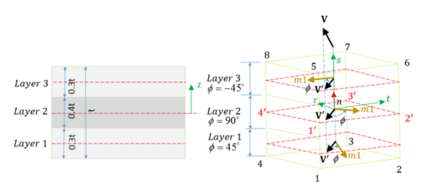
- is the angle (in degrees) between the first direction of orthotropy and projection of reference vector on the shell mean plane for layer i.
- Material used for
layer
- Material law type used in Mat_IDi can be different for each layer.
- For Isolid= 15, the material law number defined in /PART will be used to compute the contact interface stiffness and the hourglass stresses.