Model Preparation
- Mesh quality
- Spring definition
- Intersections and penetrations in interface definition
- Checking the incompatible kinematic conditions:
- No common secondary nodes between rigid bodies
- Only "free" main node
- Spherical inertia for the small ones
- Mass and center of gravity
- Thickness of the parts
- Initial velocity value and direction
- Rigid wall normal
- Material law: units system consistency
- Free nodes
- Monitored volume:
- Closed volume
- Positive volume
- Connectivity between parts
- Mesh sizes between connected parts
Some basic rules to create a valid model are presented.
Mesh Quality
The Mesh Recommendations discussed in Finite Elements should be respected. The shell mesh must be as homogenous as possible. It is not recommended to use different shell formulations for a given physical part. For very fine meshes, it is recommended to use fully-integrated elements or a physical stabilization method (/PROP/SHELL). Triangle shells are avoided. If the mesh includes triangles due to a difficult mesh, it is recommended to reduce its number to 5% per part.
Material Check
- Is the material in the right
unit system?
- For metallic
parts:
40 GPa < Modulus < 210 GPa
1.8e-6 kg/mm3 < Density < 7.8e-6 kg/mm3
- For plastic parts (PP,
PC-ABS, PP GF30%...):
0.9 GPa < Modulus < 13 GPa
9e-7 kg/mm3 < Density < 1.6e-6 kg/mm3
- For foam:
1e-8 kg/mm3 < Density < 1e-7 kg/mm3
- For metallic
parts:
- Is it a proven material from
the material database?
Realistic material data needs be input.
- Check for these common
problems in material.
- Negative slopes in stress-strain curve
- Elastic material being assigned to deformable parts
- Unrealistic yield stress (> 2 GPa)
- Failure is not defined and elements of plastic or metallic parts are stretching unrealistically (plastic strain > 1)
Some of the checks mentioned above can be performed in HyperCrash.- Unit consistency can be done with the contour check in the quality panel.
- The check “Part is not integrated in rbody for LAW1” finds parts which are deformable and using material LAW1, which can become unstable, if the deformation becomes large.
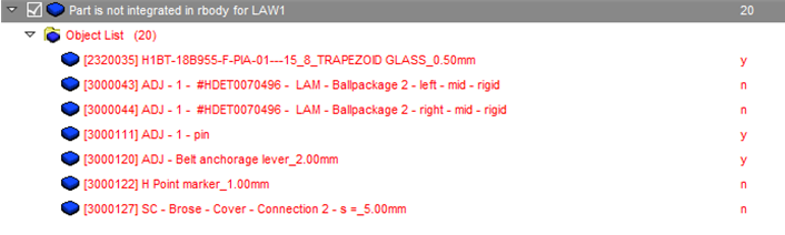
Figure 1.
Solid and Shell Definition
- For parts using
elastic-plastic material law (LAW2, LAW27, LAW36, and so on).
- Ishell=24, Ismstr=4, Iplas=1, Ithick=1, N=5
- For solid parts using
elastic-plastic material law (LAW2, LAW27, LAW36, and so on).
- For hexahedral elements:
Isolid=24, Ismstr=4
- For first order tetra
elements:
Isolid=1, Itetra=0 or 1
- For second order tetra
elements:
Isolid=1
- For hexahedral elements:
- For solid parts using
hyperelastic material (LAW42, LAW69, and so on)
- For hexahedral
elements:
Isolid=24, Ismstr=10, Icpre=1, IHKT=2
- For tetra elements:
Isolid=1, Ismstr=10
- For hexahedral
elements:
- For foam:
- Material LAW38:
Isolid=24, Ismstr=10
- Material LAW70:
Isolid=1 or 17, Ismstr=1 or 11
- For foam modeled with tetra elements, Itetra should not be set to 1 as foam is highly compressible.
- Material LAW38:
- For fabric:
- LAW19 tria elements:
Ishell=4, Ismstr=1, dm=0.2, N=1
- LAW58 tria elements:
Ishell=4, Ismstr=4, dm=0.2, N=1
- LAW19 tria elements:
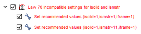
Figure 2. LAW70

Figure 3. LAW42
Spring Definition
- With regard to mass distribution over a one-dimensional bar, the inertia
will have upper and lower limits:
(1) The lower limit is the inertia of a uniform mass distributed bar. The upper limit gives the inertia of a bar with two extremity masses m/2. As the springs are also used to model bolts and spot welds, you can go beyond these limitations and write:(2) - The cross-section of a spring can be computed either by or . If the ratio between the two computed values is greater than 100, the inconsistency may result some trouble.
- In the spring property, for a negative strain the force must be negative and for a positive strain, it must be positive. Otherwise, the spring generates energy during computation.
- If the tangent stiffness is negative for a nonlinear elastic spring, there is a risk of instability especially if vibrating in the negative slope zone (energy error may become positive and increase).
- If the maximum slope of the curve (so the maximum stiffness) is greater than the initial stiffness, unloading in the zone of maximum slope will be false (see Modeling Tools).
- Very high stiffness in spring
elements can cause low timestep and instability. For example, the following check in HyperCrash allows to identify the spring element that have unusually high stiffness in tension (1000 kN/mm) and rotation (10000 kN.mm/rad).Note: Property that is referenced in parts of the dummy / barrier models should be ignored.
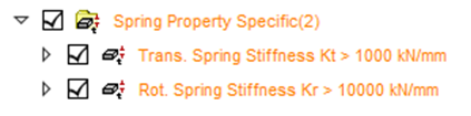
Figure 4.
Beam Consistency
Intersections and Penetrations in Interfaces
Initial mesh intersections create unrealistic connections. Moreover, this can cause locking situations leading to computation failure.
Initial penetrations are due to the interface gap definition. They lead to unrealistic and uncontrolled internal forces which may cause local plastic strains in the beginning of the computation. The structure is then locally less stiff.
Altair pre-processor tools can be used to detect and remove intersections and initial penetrations. A model containing many initial penetrations cannot be considered as valid. After corrections, if a few number of initial penetrations remain, the flag Inacti =1 can be activated in /INTER/TYPE7. In this case, the interface stiffness for the nodes initially penetrated is deactivated.
- Best practice
(recommended):
- For interface TYPE7,
11 and 19:
- Istf=4, Stmin= 1, Idel = 1 or 2, Inacti=6, Iform=2, Gapmin ≥ 0.49
- There is no intersection in the areas where the simulation fails
- Penetrations are not too deep (check residual distance in HyperCrash/HyperMesh). It should not be below 0.1mm.
- For interface TYPE2:
- Use Spotflag= 28 if main is shell or secondary node has rotational DOF and main does not (solid)
- Use Spotflag= 27 if both secondary and main do not have rotational DOF (solid)
- Idel should be set to 1 for all cases
- For interface TYPE7,
11 and 19:
Rigid Body Definition
- Never use a node of the mesh as a main node for a rigid body
- A rigid body made of two secondary nodes requires using the spherical inertia flag (Ispher =1 in /RBODY)
- Be aware that the main node may move when initializing the rigid body in Radioss Starter
Most rigid body definition problems can be detected and corrected using Altair pre-processor tools.
Incompatible Kinematic Conditions
Incompatible conditions may results in an increase of the total energy and non-reproducibility of results in parallel computation even if /PARITH/ON is used. Radioss Starter detects the potential incompatible conditions that must be controlled by you.
Parallel Computation
The option /PARITH/ON must be used when using multi-processors. If it is not used, the problems will be difficult to reproduce and may appear and disappear.
Comments
- Using Inacti =1 makes the model softer.
- Never put free nodes in the interfaces. The selection of surfaces in interface definition must be done with shells and solids elements (or parts) and not nodes.