
Model Debugging
Here are some guidelines to find the origin of computation problems.
First, note that Radioss Explicit Solver allows resolving high nonlinear dynamic problems; a computation may be wrong even if the run does not fail. If the calculation goes to the end, it illustrates a good numerical behavior but not inevitably a good physical response. However, it is required to receive the message "Normal termination" at the end of the Engine output file, to validate numerical resolution procedures.
- Numerical stability
- Physical behavior
- Physical reliability
The numerical stability is ensured if a message "Normal termination" and energy and mass balance are verified.
- How dependent is the result on friction?
- How dependent is the model on rupture phenomena?
- How dependent is the result on unknown material parameters?
- How dependent is the model on other phenomena that are difficult to simulate?
Divergence
- Positive energy error (except for the first cycle)
- Negative energy error by more than 15% (except for the first cycle)
- Kinematic time step activation in interface TYPE7
- Time step given by a rigid body
- Unexplained changes in time step
- Quick increase of mass
- Quick divergence
- Energy error increase is often exponential. The calculation fails in few cycles.
- Late divergence
- Time step is too low. The structure is distorted and high penetrations in a lot of interfaces are observed.
- Slow divergence
- The final error is not necessarily the cause of divergence.
It is important to find which event triggered the problem. The event just before the divergence needs to be checked. If a strange behavior is observed for a given part, the connected parts and previous events also have to be studied.
Run Problems
- Run Stops At Cycle 0
- The data is not written in the Engine output file runname_0001.out. This is generally due to bad running procedure when the Restart file cannot be read properly.
- Run Stops After Few Cycles
- The data is written in the Engine output file runname_0001.out. The origin of the problem can either be the incompatible kinematic conditions (for example: rigid bodies with a common secondary node) or out of bounds values in material or element properties; although, initial penetrations may be the cause.
- Run Stops During Computation
- First check the required disk space, then the behavior just before and
after divergence can be studied. The time step evolution and the energy
error need to be observed.
- An animation
file before run terminates. This is very useful to identify
areas:
- Where the velocity is out of range (>> 100 m/s)
- Mass is getting added
- Deformation is excessive (check plastic strain)
- Stress is unrealistic (> 2 Gpa) In HyperView, review the animation and check visually for any obvious issues:
- Velocity is not applied to all the nodes of the vehicle
- Incorrect boundary conditions
- Missing connections (seatbelt is not connected properly, and so on)
- Review basic contours:
- von Mises Stress: check for values that are out of bounds
- Added Mass: check for very big mass
- Velocity: check for very big velocity In many cases, the nodes with the highest velocity or high mass added will be in the same area.
- A point in
the T01 file. This is useful to identify:
- The part which have sudden increase in internal/kinetic energy. Plot the internal and kinetic energy of all the parts in HyperGraph (you need to put all the parts in time history).
- Plot global energy balance to identify, if the divergence is due to the internal energy, kinematic energy, external work force.
- Information
at the end of the listing file
(_0001.out).
For example, in the case below, the information provided at the end of the _0001.out is very useful in trying to understand the area of the model causing the simulation to stop.
The solver reports:- Which parts have the highest kinetic (1) / internal energy (2)
- Which nodes have the highest velocity (3) / mass change (4)
Figure 1. 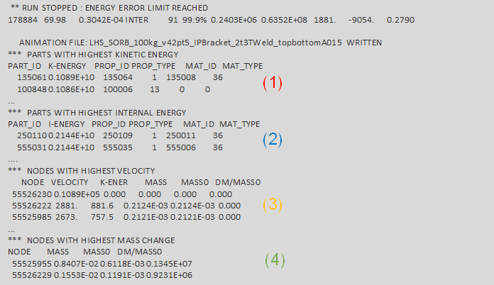
For example, in the case below, before the simulation fails with an error termination, the following message may be printed in the _0001.out:CYCLE TIME TIME-STEP ELEMENT ERROR I-ENERGY K-ENERGY T K-ENERGY R EXT-WORK MAS.ERR 62100 18.53 0.2985E-03 SOLID 230440718 -1.3% 0.3484E+05 0.1313E+06 109.7 1523. RUPTURE OF SOLID ELEMENT NUMBER 230025298 DELETE CONNECTION SOLID ELEMENT 110010956, ENERGY= 4.732011155E-05 RUPTURE OF SOLID ELEMENT NUMBER 230024559 **WARNING MINIMUM TIME STEP 0.5976E-05 IN INTERFACE NB 2300040(DTMIN= 0.1000E-04) SECONDARY NODES NB 230373002 230373019 MAIN NODES NB 230373003 230373004 DELETE SECONDARY LINE FROM INTERFACE
An initial intersection causes high distortion and eventually ERROR termination.Figure 2. 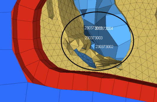
For example, in the case below, the run is killed, due to contact with a rigid causes the ERROR termination. The output file prints:Figure 3. 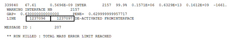
Figure 4. 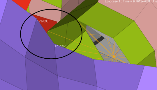
- An animation
file before run terminates. This is very useful to identify
areas:
- Negative Volume Message
- This is mainly due to high deformation of solid meshes. Fully-integrated brick elements are especially affected by this problem which may be caused by a bad interface behavior or bad material definitions. In any case, the use of co-rotational formulation is recommended to avoid bad shear deformation response.