/LOAD/PBLAST
Block Format Keyword Provides a fast way to simulate air blast pressure on a structure.
The Air Blast incident pressure is fitted from experimental data, then blast pressure is deduced from surface orientation to the detonation point. You must provide detonation point, detonation time and equivalent TNT mass.
This is a simplified loading method because the arrival time and incident pressure are not adjusted for obstacles. It also does not take into account confinement or ground effects.
Format
| (1) | (2) | (3) | (4) | (5) | (6) | (7) | (8) | (9) | (10) |
|---|---|---|---|---|---|---|---|---|---|
| /LOAD/PBLAST/load_ID/unit_ID | |||||||||
| load_title | |||||||||
| surf_ID | Exp_data | I_tshift | Ndt | IZ | Imodel | Node_ID | |||
| xdet | Ydet | Zdet | Tdet | WTNT | |||||
| Pmin | Tstop | ||||||||
| Ground_ID | Ishape | ||||||||
Definition
| Field | Contents | SI Unit Example |
|---|---|---|
| load_ID | Load
identifier. (Integer, maximum 10 digits) |
|
| unit_ID | (Optional) Unit identifier. (Integer, maximum 10 digits) |
|
| load_title | Load
title. (Character, maximum 10 digits) |
|
| surf_ID | Surface
identifier. (Integer, maximum 10 digits) |
|
| Exp_data | Experiment data flag.
(Integer, maximum 10 digits) |
|
| I_tshift | Time shift flag.
(Integer) |
|
| Ndt | Number of intervals
for minimum time step.
Where, is the duration of positive phase. Default = 100 (Integer) |
|
| IZ | Scaled Distance update
with time.
(Integer) |
|
| Imodel | Modeling flag.
(Integer) |
|
| Node_ID | Node identifier
defining detonation point. If defined, the flags Xdet, Ydet and Zdet are ignored. |
|
| Xdet | Detonation Point
X-coordinate. Ignored if Node_ID ≠ 0. Default = 0.0 (Real) |
|
| Ydet | Detonation Point
Y-coordinate. Ignored if Node_ID ≠ 0. Default = 0.0 (Real) |
|
| Zdet | Detonation Point
Z-coordinate. Ignored if Node_ID ≠ 0. Default = 0.0 (Real) |
|
| Tdet | Detonation
time. Default = 0.0 (Real) |
|
| WTNT | Equivalent TNT
mass. (Real) |
|
| Pmin | Minimum
pressure. Default = 0.0 (Real) |
|
| Tstop | Stop time. Default = 1020 (Real) |
|
| Ground_ID | Surface identifier for
ground definition. Ignored if Exp_data=1. Surface type is /SURF/PLANE Default: Origin =(0,0,0), normal=(0,0,H) |
|
| Ishape | Propagation shape. 10
|
Comments
- Modeling situation is set with
Exp_data flag. You provide explosion data
(Xdet,
Ydet,
Zdet), explosion mass
(WTNT) target surface
(surf_ID), and detonation time
(Tdet). All other
parameters and flags have default values.If Exp_data=3, explosive height must be defined.
Figure 1. 
At a given point over the user surface, the corresponding radius and the explosive mass WTNT is used to determine characteristic values of the blast wave (arrival time , maximum pressure Pmax, positive duration , impulse , ...). Both incident wave and reflected wave are to follow Friedlander’s equation:- If
Imodel =
1 (Friedlander model)
- If
Imodel =
2 (modified Friedlander model)
Where, are experimentally known at a given scaled distance . 3
With the modified Friedlander model (Imodel=2), ‘b’ is a decay parameter introduced to fit the positive impulse.
'b’ is solved such as:and its lower bound is 0.0.Figure 2. Blast profile from Friedlander equation 
- If
Imodel =
1 (Friedlander model)
- The fitted time history function
and
are also used to compute blast loading
at a given face centroid Z’ (Figure 3).
2
Figure 3. Blast pressure applied on a face centroid Z’ . depends on face orientation 
Where, is the angle between the surface segment (centroid Z’) and the direction to detonation point.
This means that blast pressure is equal to reflected pressure if segment is directly facing the detonation point, and equal to incident pressure if segment is not facing the detonation point. This modeling is simple because arrival time and incident pressure are not adjusted with shadowing of the related structure. It also does not into account confinement and tunnel effect.
This also requires the surface to have outward normal vector.
- If Iz =1, R is constant and computed during Starter at time=0.00. When Iz =2, is updated for each cycle during Engine computation.
- If WTNT is not set, the mass is zero and no pressure will be loaded on the related surface.
- If modeled explosive is not TNT, an equivalent TNT mass must be provided.
- The experimental data uses the unit system {cm, g, }. The units defined in /BEGIN will be used to convert the experimental data units to the model units. Therefore, the units defined in /BEGIN must correctly match the units used in the model.
- It is possible to skip computation time from
to
. The shift value is automatically computed
during Starter execution. To disable a computation up to
, the I_tshift value must be
equal to 2.
Figure 4. I_tshift enables to skip computation time up to first wave arrival time 
- The
parameter can impose a minimum time step, if
structural one is not large enough. Imposing
ensures that there are sufficient time steps
during positive phase, that is, during the
exponential
decrease of the blast wave. By default,
.
Figure 5. 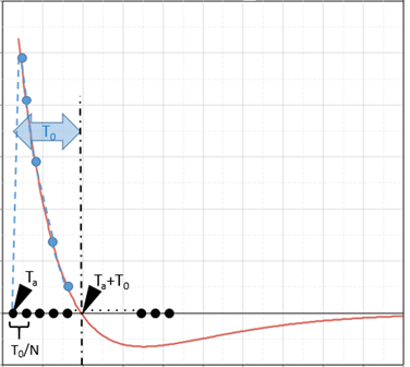
- Parameter
was introduced to keep positive part of the
Friedlander blast model.
Figure 6. Parameter used to keep only overpressure (positive part of the loading) 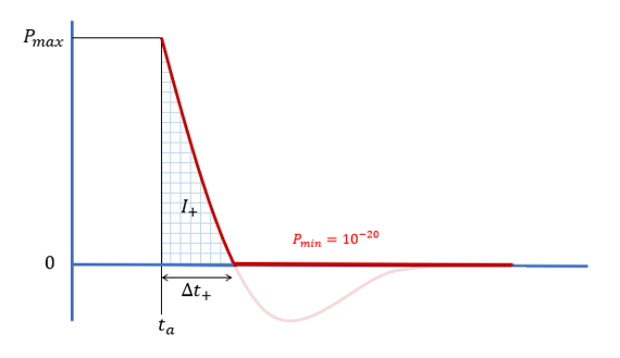
- Propagation shape.
Figure 7. Ishape = 1: Spherical propagation (above the ground) 
Figure 8. Ishape = 2: Spherical propagation (ground ignored) 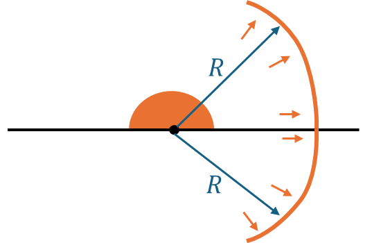
Figure 9. Ishape = 3: Straight blast front propagation (above ground)