Block Format Keyword This entry provides a simple way to simulate hydrodynamic fluid pressure on a structure. The
fluid pressure is calculated according to the specified fluid velocity, orientation of the
structural surface against the fluid vector and the height of the fluid column above the
surface of the structure.
Format
(1)
(2)
(3)
(4)
(5)
(6)
(7)
(8)
(9)
(10)
/LOAD/PFLUID/load_ID/unit_ID
load_title
surf_ID
sens_ID
fct_hsp
Ascalex_hsp
Fscaley_hsp
Dir_hsp
frahsp_ID
fct_pc
Ascalex_pc
Fscaley_pc
fct_vel
Ascalex_vel
Fscaley_vel
Dir_vel
fravel_ID
Definition
Field
Contents
SI Unit Example
load_ID
Load block
identifier.
(Integer, maximum 10 digits)
unit_ID
Unit Identifier.
(Integer, maximum 10 digits)
load_title
Load block title.
(Character,
maximum 100 characters)
surf_ID
Surface
identifier.
(Integer)
sens_ID
Sensor
identifier.
(Integer)
fct_hsp
Hydro-static pressure as a
function of the fluid column height above the structural
surface.
(Integer)
Ascalex_hsp
Abscissa scale factor for
fct_hsp.
Default = 1.0 (Real)
Fscaley_hsp
Ordinate scale factor for
fct_hsp.
Default = 1.0 (Real)
Dir_hsp
Vertical (gravitational)
direction of the water column above the structural surface (input X, Y or
Z).
(Text)
frahsp_ID
Frame identifier for the vertical
(gravitational) direction of the water column above the structural
surface.
(Integer)
fct_pc
Hydrodynamic drag coefficient as
a function of time. 4
(Integer)
Ascalex_pc
Abscissa scale factor for
fct_pc.
Default = 1.0 (Real)
Fscaley_pc
Ordinate scale factor for
fct_pc.
Default = 1.0 (Real)
fct_vel
Fluid velocity as a function of
time.
(Integer)
Ascalex_vel
Abscissa scale factor for
fct_vel.
Default = 1.0 (Real)
Fscaley_vel
Ordinate scale factor for
fct_vel.
Default = 1.0 (Real)
Dir_vel
Direction of fluid velocity
(input X, Y or Z).
(Text)
fravel_ID
Frame identifier for the fluid
velocity direction.
(Integer)
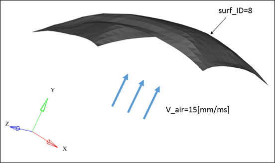
Example (Wind Effect)
In this example, /LOAD/PFLUID is used to simulate wind (with velocity
15[mm/ms]) effect on textile. Figure 1.
#RADIOSS STARTER
#---1----|----2----|----3----|----4----|----5----|----6----|----7----|----8----|----9----|---10----|
/UNIT/1
unit for load
#              MUNIT               LUNIT               TUNIT
                 kg                  mm                  ms
#---1----|----2----|----3----|----4----|----5----|----6----|----7----|----8----|----9----|---10----|
/LOAD/PFLUID/1/1
Wind effect
#  surf_ID   sens_ID
         8         0
#  fct_hsp                   Ascalex_hsp         Fscaley_hsp
         0                             0                   0
#  Dir_hsp frahsp_ID
                   0
#   fct_pc                    Ascalex_pc          Fscaley_pc
         2                             0                   2
#  fct_vel                   Ascalex_vel         Fscaley_vel
         3                             0                  15
#  Dir_vel fravel_ID
         Y         0
#---1----|----2----|----3----|----4----|----5----|----6----|----7----|----8----|----9----|---10----|
/FUNCT/2
Air density
#                  X                   Y
                   0              1.2E-9
                1000              1.2E-9
#---1----|----2----|----3----|----4----|----5----|----6----|----7----|----8----|----9----|---10----|
/FUNCT/3
Air velocity
#                  X                   Y
                   0                   1
                1000                   1
#---1----|----2----|----3----|----4----|----5----|----6----|----7----|----8----|----9----|---10----|
#ENDDATA
Comments
The fluid pressure applied to each
element of the structural surface is computed as:(1)
Where,
Fluid density
Acceleration due to gravity
Height of the water column above an element of the structural surface
Relative fluid velocity which is normal to the element of the structural
surface
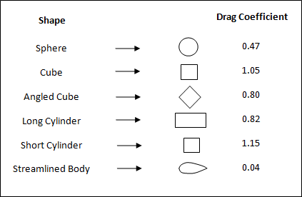
Drag coefficient for complete structural surface
The value of the drag coefficient depends on the shape of the cross-section
of the body in the direction of fluid flow (Figure 2).
Figure 2. Drag Coefficient Values for Different Shapes
The value of hydrostatic pressure () as a function of fluid column height
() above the structural surface is stated
using the function fct_hsp. If this is not defined (=0), the effect
is not accounted for (fct_hsp(altitude)=0).
Hydrodynamic pressure is calculated
with respect to the relative orientation of the fluid vector and the element
normal.(2)
Where,
Specified fluid velocity (fct_vel(t)). If not defined
(=0), the effect of fluid velocity is not accounted for (= 0)
Element velocity
Element normal
fct_pc defines the
value of as a function of time. If this is
not defined, the effect of fluid velocity is not accounted for.