
/MAT/LAW119 (SH_SEATBELT)
Block Format Keyword This orthotropic shell material is designed for 2D seatbelt element.
Format
| (1) | (2) | (3) | (4) | (5) | (6) | (7) | (8) | (9) | (10) |
|---|---|---|---|---|---|---|---|---|---|
| /MAT/LAW119/mat_ID/unit_ID or /MAT/SH_SEATBELT/mat_ID/unit_ID | |||||||||
| mat_title | |||||||||
| M | Lmin | ||||||||
| K | C | RE | |||||||
| fct_ID1 | fct_ID2 | Fscale1 | Fscale2 | ||||||
| E22 | 12 | G12 | Fscale22 | ||||||
| Ec | Tc | ||||||||
Definition
| Field | Contents | SI Unit Example |
|---|---|---|
| mat_ID | Material identifier. (Integer, maximum 10 digits) |
|
| unit_ID | (Optional) Unit identifier. (Integer, maximum 10 digits) |
|
| mat_title | Material title. (Character, maximum 100 characters) |
|
| M | Mass per unit length of the
seatbelt. (Real) |
|
| Lmin | Minimum length. Only used with
/SLIPRING/SHELL. (Real) |
|
| K | Linear loading and unloading
stiffness per unit length. Used only if . (Real) |
|
| C | Linear Damping coefficient per unit
length. If not defined, a small amount of damping is automatically applied. (Real) |
|
| RE | Reduction factor value for
compression behavior. Minimum value, RE > 0.001. Default =1.0 (Real) |
|
| fct_ID1 | Function identifier defining
loading force versus engineering strain or table identifier for
set of strain rate dependent loading curve
f(ε). (Integer) |
|
| fct_ID2 | Function identifier defining
unloading force versus engineering strain f(ε). Not used when element is inside slipring or retractors. (Integer) |
|
| Fscale1 | Scale factor for f(ε) for fct_ID1. Default = 1.0 (Real) |
|
| Fscale2 | Scale factor for f(ε) for fct_ID2. Default = 1.0 (Real) |
|
| E22 | Young’s modulus in transverse
direction. 8
(Real) |
|
| 12 | Poisson’s ratio. Default = 0.2 (Real) |
|
| G12 | Shear modulus. 9 (Real) |
|
| Fscale22 | Stiffness scaling factor for
transverse direction. Not used in current version. Default = 0.0 (Real) |
|
| Ec | Young’s modulus for coating layer.
11 Default = 0.0 (Real) |
|
| Poisson’s ratio for coating
layer. Default = 12 (Real) |
||
| Tc | Thickness for coating
layer. (Real) |
Example (Seatbelt)
#RADIOSS STARTER
#---1----|----2----|----3----|----4----|----5----|----6----|----7----|----8----|----9----|---10----|
/UNIT/1
Seatbelt
                  Mg                  mm                   s
#---1----|----2----|----3----|----4----|----5----|----6----|----7----|----8----|----9----|---10----|
/MAT/SH_SEATBELT/1/1
Seatbelt
#            Density                Lmin
                1E-6                   0
#              KTens               CTens                  RE
               10000                 1.1                 1.0
#  fct_ID1   fct_ID2             Fscale1             Fscale2
         0         0                   0                   0
#                E22                NU12                 G12            Fscale22
                   0                   0                   0                   0
#                 Ec                 NUC                  TC
                   0                   0                   0
#---1----|----2----|----3----|----4----|----5----|----6----|----7----|----8----|----9----|---10----|
#ENDDATA
/END
#---1----|----2----|----3----|----4----|----5----|----6----|----7----|----8----|----9----|---10----|
Comments
- This material law is orthotropic and can only be used with /PROP/TYPE9 (SH_ORTH). The seatbelt main direction is direction 1 and the transverse direction is direction 2. The flag IP is automatically set to 24, if the property is used only for seatbelt elements. The main direction (direction 1) is defined from node 1 and node 2 or derived from skew_ID defined in property.
- A 2D seatbelt element is, in fact, a combination
of seatbelt springs elements and seatbelt shells. The longitudinal stiffness
is mainly carried by springs (99%), whereas transverse stiffness is carried
by the shells. The springs are automatically generated on the edges of the
shell elements corresponding to the seatbelt main direction (direction 1).
If an edge is common to 2 shells, then only 1 spring is generated.
Figure 1. 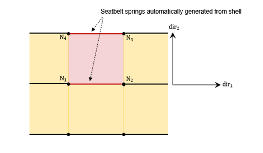
- The tension behavior can be defined either as linear elastic, if K > 0 or nonlinear fct_ID1= 0. It corresponds to the total stiffness of the seatbelt.
- fct_ID2 is used for the unloading and reloading of the seatbelt. If fct_ID2 is not defined (fct_ID2 > 0), fct_ID1 is also used for unloading and reloading.
- fct_ID1 and fct_ID2 must be defined for positive strain only.
- The stiffness per unit length is the stiffness of the whole seatbelt. It is internally computed as a Young's modulus using the section of the seatbelt that is automatically computed. As the section (width * thickness) of the belt is internally computed, the same material can not be applied to several seatbelts having different sections.
- The seatbelt Young's modulus is automatically computed from the input stiffness defined in the seatbelt direction (either by K or the maximum slop of the curve fct_ID1 if defined).
- Default value for transversal modulus
E22 is defined as a percentage of
stiffness of the belt.
- Default value for shear modulus is defined as a
small percentage of stiffness of the belt.
- Minimum length Lmin is used only in case of sliprings (/SLIPRING/SHELL) to prevent stiffness becoming infinite and causing the time step to drop.
- When coating is used, the number of the integration points must be set to N=3 in the shell property (/PROP/TYPE9).