/MAT/LAW122 (MODIFIED_LADEVEZE)
Block Format Keyword A simple unidirectional composite ply model, accounting for orthotropic elasticity and plasticity. Fiber and matrix damage are considered, including strain rate effect.
Format
| (1) | (2) | (3) | (4) | (5) | (6) | (7) | (8) | (9) | (10) |
|---|---|---|---|---|---|---|---|---|---|
| /MAT/LAW122/mat_ID/unit_ID or /MAT/MODIFIED_LADEVEZE/mat_ID/unit_ID | |||||||||
| mat_title | |||||||||
| ISH | ITR | IRES | |||||||
| M | A | ||||||||
| IBUCK | |||||||||
| IFUNCD1 | b | ||||||||
| DMAX | |||||||||
| IFUNCD2 | |||||||||
| IFUNCD2C | |||||||||
| LTYPE11 | LTYPE12 | LTYPER0 | |||||||
| FCUT | |||||||||
Definition
| Field | Contents | SI Unit Example |
|---|---|---|
| mat_ID | Material identifier. (Integer, maximum 10 digits) |
|
| unit_ID | (Optional) Unit
identifier. (Integer, maximum 10 digits) |
|
| mat_title | Material title. (Character, maximum 100 characters) |
|
| Initial
density. (Real) |
||
| Young’s modulus in fiber direction
1 for tension. (Real) |
||
| Young’s modulus in matrix direction
2. (Real) |
||
| Young’s modulus in matrix direction
3. (Real) |
||
| Shear modulus in the plane
12. (Real) |
||
| Shear modulus in the plane
23. (Real) |
||
| Shear modulus in the plane
13. (Real) |
||
| Poisson’s ratio in the plane
12. (Real) |
||
| Poisson’s ratio in the plane
23. (Real) |
||
| Poisson’s ratio in the plane
31. (Real) |
||
| Young’s modulus in fiber direction
1 for compression. (Real) |
||
| Compressive factor of the modulus
correction. (Real) |
||
| ISH | Shear matrix damage flag.
(Integer) |
|
| ITR | Transverse matrix damage flag.
(Integer) |
|
| IRES | Return mapping algorithm flag.
(Integer) |
|
| Initial yield stress. Default = 1020 (Real) |
||
| Hardening
modulus. (Real) |
||
| M | Hardening
exponent. (Real) |
|
| A | Shear and transverse plasticity
coupling factor. (Real) |
|
| Tensile initial damage strain in
fiber direction 1. Default = 1020 (Real) |
||
| Tensile ultimate damage strain in
fiber direction 1. Default = 2*1020 (Real) |
||
| Tensile ultimate damage in fiber
direction 1. (Real) |
||
| Compression initial damage strain
in fiber direction 1. Default = 1020 (Real) |
||
| Compression ultimate damage strain
in fiber direction 1. Default = 2*1020 (Real) |
||
| Compression ultimate damage in
fiber direction 1. (Real) |
||
| IBUCK | Buckling damage matrix on fiber in
compression flag.
(Integer) |
|
| IFUNCD1 | Matrix shear tabulated damage
function identifier. (Integer) |
|
| Damage saturation for matrix shear
exponential damage. (Real) |
||
| Initial matrix shear damage
threshold / Abscissa scale factor for tabulated
damage. Default = 1020 or 1.0 (Real) |
||
| Critical matrix shear damage
limit. (Real) |
||
| b | Shear/transverse matrix damage
coupling factor. Default = (Real) |
|
| DMAX | Damage maximum allowed
value. (Real) |
|
| Elementary shear damage
value. Default = 1020 (Real) |
||
| Brittle damage limit for
fiber-matrix interface. Default = 1020 (Real) |
||
| IFUNCD2 | Tension transverse matrix tabulated
damage function identifier. (Integer) |
|
| Damage saturation for transverse
matrix exponential damage in tension. (Real) |
||
| Initial transverse matrix damage
threshold in tension / Abscissa scale factor for tabulated
damage. Default = 1020 or 1.0 (Real) |
||
| Critical transverse matrix damage
limit in tension. (Real) |
||
| IFUNCDC2 | Compression transverse matrix
tabulated damage (shells only) function
identifier. (Integer) |
|
| Damage saturation for compression
transverse matrix exponential damage (shells
only). (Real) |
||
| Initial transverse damage threshold
in compression / Abscissa scale factor for tabulated damage
(shells only). (Real) |
||
| Critical transverse damage limit in
compression (shells only). (Real) |
||
| Reference strain rate for fiber
direction 1. Default = 1.0 (Real) |
||
| First parameter for Young’s modulus
strain rate dependency in fiber direction
1. (Real) |
||
| Second parameter for Young’s
modulus strain rate dependency in fiber direction
1. (Real) |
||
| First parameter for rupture strain
rate dependency in fiber direction 1. (Real) |
||
| Second parameter for rupture strain
rate dependency in fiber direction 1. (Real) |
||
| Reference strain rate for shear and
transverse directions. Default = 1.0 (Real) |
||
| First parameter for Young’s modulus
strain rate dependency in matrix transverse direction
2. (Real) |
||
| Second parameter for Young’s
modulus strain rate dependency in matrix transverse direction
2. (Real) |
||
| First parameter for shear modulus
strain rate dependency in plane 12. (Real) |
||
| Second parameter for shear modulus
strain rate dependency in plane 12. (Real) |
||
| Reference strain rate for initial
yield stress. Default = 1.0 (Real) |
||
| First parameter for initial yield
stress strain rate dependency. (Real) |
||
| Second parameter for initial yield
stress strain rate dependency. (Real) |
||
| LTYPE11 | Strain rate dependency law type for
fiber direction 1.
(Integer) |
|
| LTYPE12 | Strain rate dependency law type for
shear and transverse directions.
(Integer) |
|
| LTYPER0 | Strain rate dependency law type for
initial yield stress.
(Integer) |
|
| FCUT | Equivalent strain rate cutoff
frequency. Default = 5 kHz (Real) |
Example (Steel)
#RADIOSS STARTER
#---1----|----2----|----3----|----4----|----5----|----6----|----7----|----8----|----9----|---10----|
/UNIT/1
Test unit
                  Mg                  mm                   s
#---1----|----2----|----3----|----4----|----5----|----6----|----7----|----8----|----9----|---10----|
/MAT/LAW122/1/1
Steel
#        Init. dens.
              1.8E-9
#                 E1                  E2                  E3                 G12                 G23
              135000                1000                1000                4000                4000
#                G31                NU12                NU23                NU31
                4000                0.33                 0.1                0.33
#                E1C               GAMMA                 ISH                 ITR                IRES
              138000              1.7E-4                   0                   0                   2
#              SIGY0                BETA                   M                   A
                  20              0.7986              0.5166                0.33
#            EPS_FTI             EPS_FTU                DFTU
               0.002              0.0025                 1.0
#            EPS_FCI             EPS_FCU                DCFU               IBUCK
              0.0104              0.0105                 1.0                   1
#            IFUNCD1               DSAT1                  Y0                  YC                   B
                                                       0.158                0.05
#               DMAX                  YR                 YSP
                0.95              1.5811              1.0e20
#            IFUNCD2               DSAT2                 Y0P                 YCP
                                                       0.158                0.05
#           IFUNCD2C              DSAT2C                Y0PC                YCPC
                                                       0.158                0.05
#             EPSD11                 D11                 N11                D11U                N11U

#             EPSD12                 D22                 N22                 D12                 N12

#             EPSDR0                 DR0                 NR0             LTYPE11   LTYPE12   LTYPER0

#               FCUT

#---1----|----2----|----3----|----4----|----5----|----6----|----7----|----8----|----9----|---10----|
#enddata
/END
#---1----|----2----|----3----|----4----|----5----|----6----|----7----|----8----|----9----|---10----|
Comments
- The modified Ladeveze model considers a unidirectional composite ply
where fibers are to be oriented in the direction 1, and the matrix in the
transverse directions 2 and 3. This material orientation will then be
identified as
,
,
(Figure 1). The “out of plane” transverse
direction will then correspond to
-axis for shell and thickshell elements.
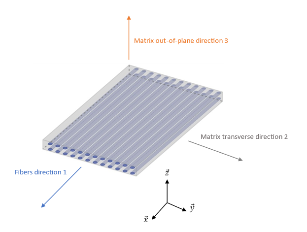
Figure 1. Unidirectional ply and its material orientation considered by /MAT/LAW122 - The elastic behavior is assumed to be orthotropic. Under 2D plane
stress conditions, for shells, the stress/strain relationship is given by:
with
Where, .
This nonlinear evolution of compression Young’s modulus in fiber direction is used to represent the effect of fiber micro buckling and misalignment. is the shear factor used for shells only and defined in the property.
For 3D stress conditions (solid elements and thickshells), the inverse of compliance matrix is used to link the stresses with the strains:(1) The same non-linearity of fiber direction Young’s modulus in compression is used.
- In fiber directions 1 (or
-axis), the behavior remains purely elastic
until damage occurs (detailed below). However, the plastic behavior of the
matrix is considered under transverse and shear loadings. The elastic limit
is introduced through a yield function that differs from solids to shells:
- For Shells:
(2) - For Solids:
(3)
Where, is a coupling factor whose value can be set to 0.33 for an isotropic resin. In this equation, the yield function is defined as:(4) This describes an isotropic hardening following a power law. The hardening modulus is numerically bounded by the value to avoid stability issues.
- For Shells:
- Like elasticity or plasticity, the damage behavior is assumed to be
orthotropic. Three damage variables are then defined:
,
and
which respectively describes the fiber
rupture, the shear matrix damage, and the transverse matrix damage.
- Fiber damage
affects the behavior along the fiber
direction 1. Under tension loading condition, fiber damage evolves
following the equations.
(5) Where, is the strain at the onset of damage, is the ultimate strain, is the ultimate damage value and is the equivalent fiber strain defined by:- For Shells:
(6) - For Solids:
(7)
The compression damage on fiber due to matrix buckling can be activated with the IBUCK flag and is described with a similar equation:(8) This fiber damage then affects the stress computation as:(9) Figure 2 shows the expected behavior in tension/compression along the fiber direction. The dashed line allows to highlight the nonlinear Young’s modulus in compression.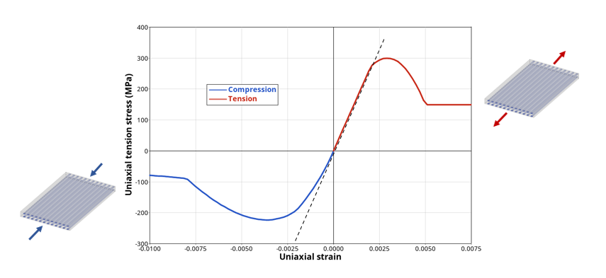
Figure 2. Tension/compression test in fiber direction showing fiber damage effect on stressNote: Along fiber direction, the behavior is purely elastic and damaging. - For Shells:
- Shear matrix damage
is introduced to represent the
debonding between matrix and fibers. Its evolution is influenced by
the energy release rate often used in Lemaitre-type damage model.
Two elastic energy rates are considered in this model.
- For Shells:
(10) Where, are the Macauley’s brackets that only considers the positive values of . However, if compression damage described below is considered (for shells only), these brackets becomes simple parenthesis.
- For Solids:
(11) This then leads to the following computation:(12) Where, is a coupling factor.
Depending on the value of the flag ISH, the shear matrix damage can evolve with different shapes.- ISH = 1: linear
shape (Figure 3)
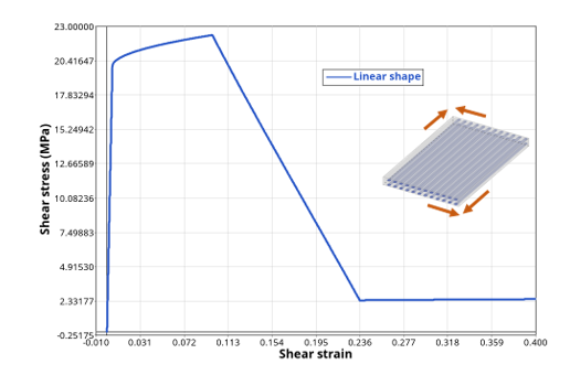
Figure 3. Shear test showing shear matrix damage effect with a linear shape - ISH = 2: exponential
shape (Figure 4)
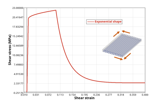
Figure 4. Shear test showing shear matrix damage effect with an exponential shape - ISH = 3: tabulated
shape (Figure 5)Where, is the function identified by IFUNCD1.
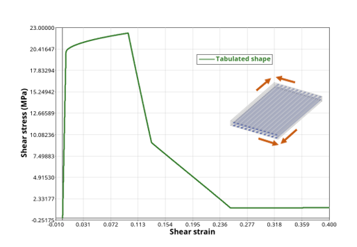
Figure 5. Shear test showing shear matrix damage effect with a tabulated shape
The shear matrix damage then affects the stresses computation as:- For Shells:
(13) - For Solids:
(14)
- For Shells:
- Transverse matrix damage
allows to represent the
microcracking of the matrix. Its evolution is very similar to shear
matrix damage, except from the fact that a different elastic energy
release rate is used:
(15) Then, like shear matrix damage, three different evolution shapes are available depending on the ITR flag value.- ITR = 1: linear
shape (Figure 6)
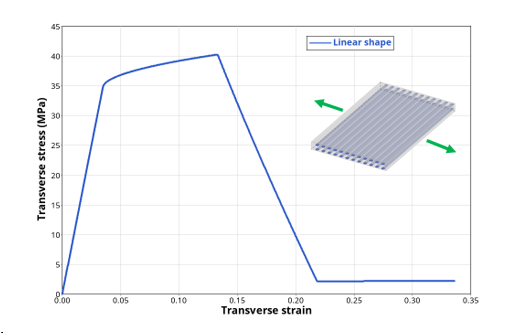
Figure 6. Tensile test in transverse direction showing transverse matrix damage effect with a linear shape - ITR = 2: exponential
shape (Figure 7)
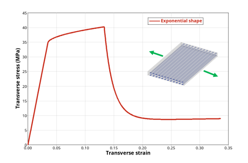
Figure 7. Tensile test in transverse direction showing transverse matrix damage effect with an exponential shape - ITR = 3: tabulated
shape (Figure 8)Where, is the function identified by IFUNCD2.
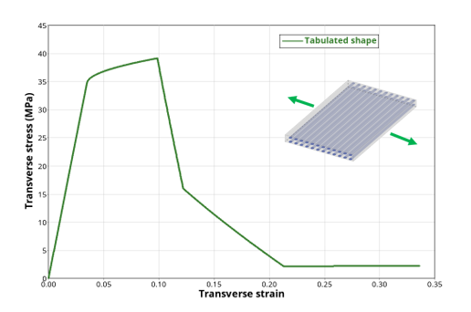
Figure 8. Tensile test in transverse direction showing transverse matrix damage effect with a tabulated shapeThis damage variable is supposed to occur in tension only. In compression, the microcracks of the matrix are assumed too close to recover the initial undamaged stiffness (Figure 9). However, for shells only, a specific transverse matrix damage evolution in compression can be described the same way using parameters: , , or IFUNCD2C.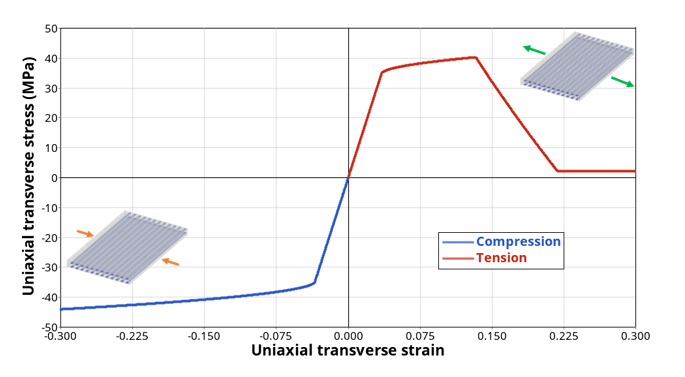
Figure 9. Tension/compression test in transverse directionThis last damage variable affects the stress computation with:(16)
- ITR = 1: linear
shape (Figure 6)
- Fiber damage
affects the behavior along the fiber
direction 1. Under tension loading condition, fiber damage evolves
following the equations.
- The last phenomenon represented in the modified Ladeveze model is
the strain rate dependency. Once again, it is assumed that the viscous
effects are not the same for the fibers and the matrix.
- In fiber direction, the viscosity affects the Young’s modulus
through the introduction of a rate factor denoted
:
(17) Where, is the equivalent strain rate and is the reference strain rate in direction 1.
The rate factor equation can take different shape depending on the value of the flag LTYPE11:- LTYPE11 = 1: power
law
(18) - LTYPE11 = 2: linear
law
(19) - LTYPE11 = 3:
logarithmic law
(20) - LTYPE11 = 4: tangent
hyperbolic law
(21)
The fibers failure can also be affected by strain rate through the introduction of the factor, whose evolution will also depend on the flag LTYPE11 using parameters and :(22) The expected behavior is detailed below in Figure 10.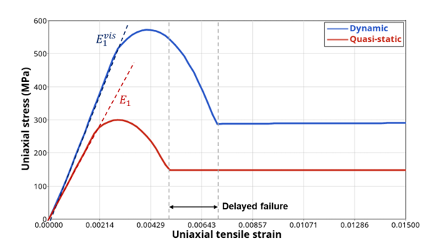
Figure 10. Strain rate effect on fibers direction behavior - LTYPE11 = 1: power
law
- In matrix direction, the shear and transverse behavior are affected
by strain rate, as well. The elasticity is then modified with the
introduction of the factors
and
as follows:
(23) You can notice that the two factors are using the same strain rate reference value and that , and are only modified for solids. The shape of the factors and will be fixed by the flag LTYPE12, and will depend respectively on the values of , and , .
The fracture energy is increased with strain rate, as well, using the same factors:(24) Note: The compression damage parameter for transverse directions and are only modified for shells. - Finally, the last parameter affected by viscous effect is the
initial yield stress, with the use of factor
.
(25) Similarly, the shape of factor is dictated by the flag LTYPER0 using parameters and .
The expected behavior for transverse matrix direction (which is similar for tension and shear) is detailed below in Figure 11.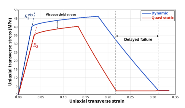
Figure 11. Strain rate effect on matrix transverse (or shear) direction behavior
- In fiber direction, the viscosity affects the Young’s modulus
through the introduction of a rate factor denoted
: