Ityp = 3
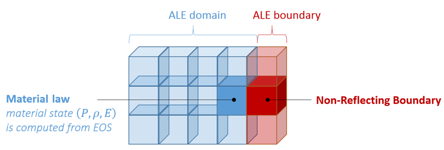
Block Format Keyword This law enables to model a non-reflecting boundary (NRF). Input card is similar to /MAT/LAW11 (BOUND), but introduces two new lines to define turbulence parameters.

Format
| (1) | (2) | (3) | (4) | (5) | (6) | (7) | (8) | (9) | (10) |
|---|---|---|---|---|---|---|---|---|---|
| /MAT/B-K-EPS/mat_ID/unit_ID | |||||||||
| mat_title | |||||||||
| Ityp | Psh | ||||||||
| (1) | (2) | (3) | (4) | (5) | (6) | (7) | (8) | (9) | (10) |
|---|---|---|---|---|---|---|---|---|---|
| c | |||||||||
| Blank Format | |||||||||
| Blank Format | |||||||||
| Blank Format | |||||||||
| fct_IDk | fct_IDe | ||||||||
| Blank Format | |||||||||
Definition
| Field | Contents | SI Unit Example |
|---|---|---|
| mat_ID | Material identifier. (Integer, maximum 10 digits) |
|
| unit_ID | Unit identifier. (Integer, maximum 10 digits) |
|
| mat_title | Material title. (Character, maximum 100 characters) |
|
| Initial density. 3 (Real) |
||
| Reference density used in
E.O.S (equation of state). Default (Real) |
||
| Ityp | Boundary condition type.
1
(Integer) |
|
| Psh | Pressure shift. 2 (Real) |
|
| c | Outlet sound speed. 1 (Real) |
|
| Characteristic length.
1 (Real) |
||
| Initial turbulent
energy. (Real) |
||
| Initial turbulent
dissipation. (Real) |
||
| fct_IDk | Function
identifier for turbulence
modeling.
(Integer) |
|
| fct_IDe | Function f
(t) identifier for energy.
(Integer) |
|
| Turbulent viscosity
coefficient. Default = 0.09 (Real) |
||
| Diffusion coefficient for
k parameter. Default = 1.00 (Real) |
||
| Diffusion coefficient for
parameter. Default = 1.30 (Real) |
||
| Ratio between Laminar
Prandtl number (Default 0.7) and turbulent Prandtl number (Default
0.9). (Real) |
Example (Gas)
#RADIOSS STARTER
#---1----|----2----|----3----|----4----|----5----|----6----|----7----|----8----|----9----|---10----|
/MAT/B-K-EPS/5
GAS OUTLET (unit: kg_m_s)
#              RHO_I               RHO_0
               .3828                   0
#     ITYP                           Psh
         3                           0.0
#                                      c                  lc
                                     605                 0.3
#blank line

#blank line

#blank line

#             Rho0k0            Rho0Eps0     fct_k   fct_eps
                  20                   0         0         0
#                Cmu             Sigma-k       Sigma-epsilon              Pr/Prt
                   0                   0                   0                   0
#blank line

/ALE/MAT/5
#     Modif. factor.
                   0
#---1----|----2----|----3----|----4----|----5----|----6----|----7----|----8----|----9----|---10----|
#enddata
/END
#---1----|----2----|----3----|----4----|----5----|----6----|----7----|----8----|----9----|---10----|
Comments
- Non-Reflecting Boundary
formulation is based on Bayliss & Turkel. 1 The objective is to impose a mean pressure
which fluctuate with rapid variations of pressure and velocity:Pressure in the far field is imposed with a function of time. The transient pressure is derived from , the local velocity field V and the normal of the outlet facet:
- density, energy, temperature, turbulent energy and dissipation are imposed with a function of time as in Ityp = 2
- if the function number is 0, the neighbor element value is used to respect continuity
- acoustic impedance will be
- typical length
is used to relax the effective
pressure towards its imposed value. It should be large compared to
the highest wave length of interest in the problem. The relaxation
term acts as high pass filter whose frequency cut-off
is:
Where, sound speed c and characteristic length are two required parameters (non zero).
- The Psh parameter enables shifting the output pressure which also becomes P-Psh. If using , the output pressure will be , with an initial value of 0.0.
- With thermal modeling, all thermal data ( , ...) can be defined with /HEAT/MAT.
- It is not possible to use this boundary material law with multi-material ALE /MAT/LAW37 (BIPHAS) and /MAT/LAW51 (MULTIMAT).