Thickness Mapping
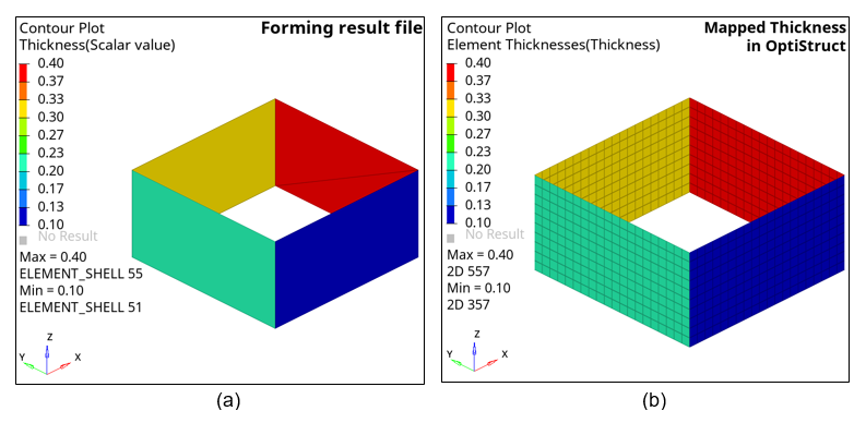
The thickness mapping feature allows the user to map the thickness data from an external forming result file to the corresponding model in OptiStruct.
Consider a situation, when a component obtained from sheet metal forming needs to be analyzed further in an assembly model, after accounting for the thickness variation from forming.
- In the OptiStruct model file, an initial thickness needs to be defined and the thickness mapping feature will overwrite a new thickness distribution for the elements specified in the thickness mapping definition.
- The thickness mapping feature works even when the following attributes
are different between the forming result file and the OptiStruct model file:
- Mesh – Element types, Element ID, Node ID, Element order
- Orientation of the components being mapped (in the presence of relocation)
Problem Setup Example
.
.
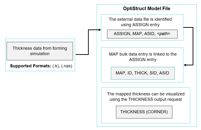
$ USING ASSIGN TO REFERENCE THE FORMING RESULT FILE
ASSIGN, MAP, 100,"forming_result.k"
$ REQUESTING THICKNESS OUTPUT FOR VISUALIZATION
THICKNESS(CORNER)=ALL
BEGIN BULK
$ DEFINITION OF MAP ENTRY
MAP, 1, THICK, 12, 100
$ SET OF ELEMENTS TO WHICH THE MAPPING MUST BE APPLIED
SET, 12, ELEM, LIST
+, ALL
.
.
Relocation
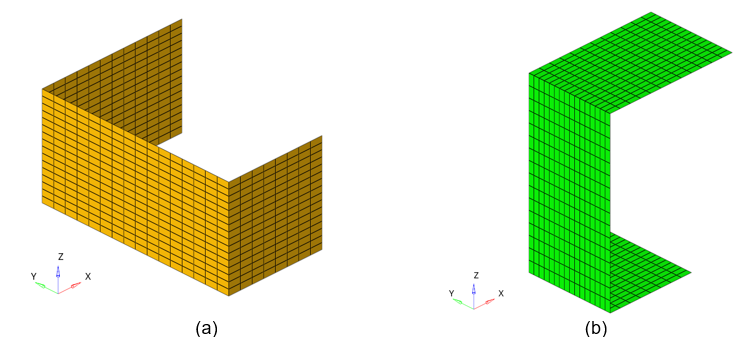
The method of relocation (RELOC) is used in cases when the model in the forming result file and the model in OptiStruct are oriented differently, in which case, the regular mapping would not work.
Input Format
| (1) | (2) | (3) | (4) | (5) | (6) | (7) | (8) | (9) | (10) |
|---|---|---|---|---|---|---|---|---|---|
| MAP | ID | TYPE | SID | ASID | SCALE | ||||
| RELOC | RTYPE | PA1 | PA2 | PA3 | PB1 | PB2 | PB3 |
There are 2 types of relocation available, which are explained below.
MATCH Option
When the orientations are different between the forming result and the OptiStruct model, the regular mapping process might not work.
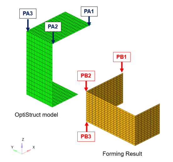
In such cases, relocation with the MATCH option can be used, by specifying RTYPE = MATCH in the continuation line. Usage of relocation with MATCH option requires the definition of 3 matching grid ID pairs, denoted by PAi in the OptiStruct model and PBi in the forming result, where (i =1, 2, 3).
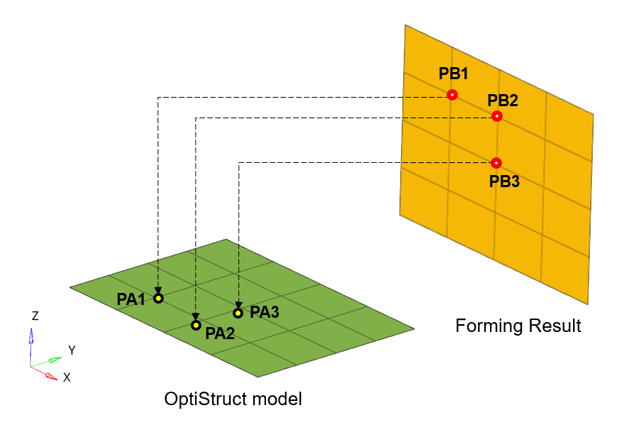
If the grid IDs defined with PA1, PA2, PA3 do not match with the grid IDs defined using PB1, PB2, PB3, respectively, OptiStruct will produce an error message.
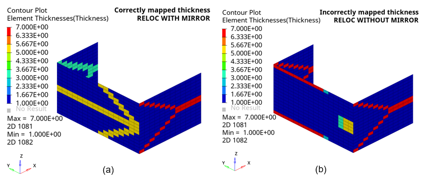
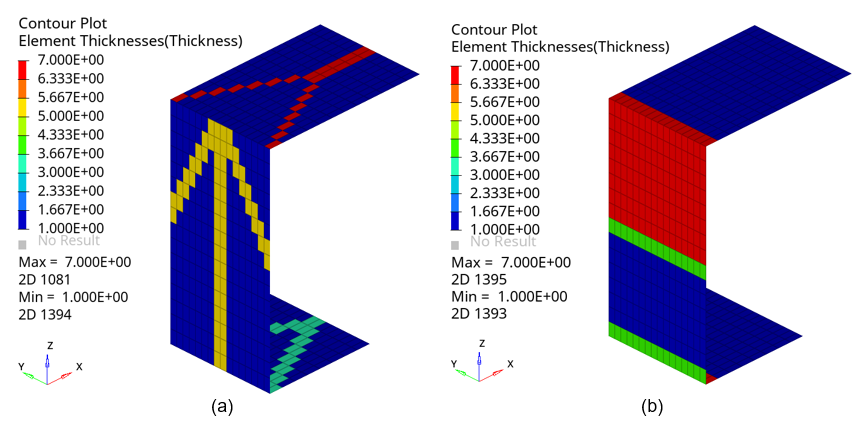
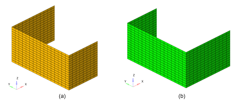
The effect of relocation with MATCH can be seen in Figure 7(a) where the thicknesses have been mapped correctly.
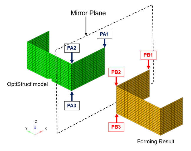
MIRROR Option
The previously discussed relocation method with MATCH will fail for cases when the forming result file and the OptiStruct model file are mirror images of each other and mapping needs to be performed.
In such cases, relocation with the MIRROR option can be used, by specifying RTYPE = MIRROR in the continuation line.
Usage of relocation with MATCH option requires the definition of 3 grid ID pairs, denoted by PAi in the OptiStruct model and PBi in the forming result, where (i =1, 2, 3).
The grid ID pairs must be defined in such a way that the points defined by PA1, PA2 and PA3 are mirror images of PB1, PB2 and PB3, respectively. The thicknesses are mirrored from the forming result file about the plane defined by PB1, PB2 and PB3.
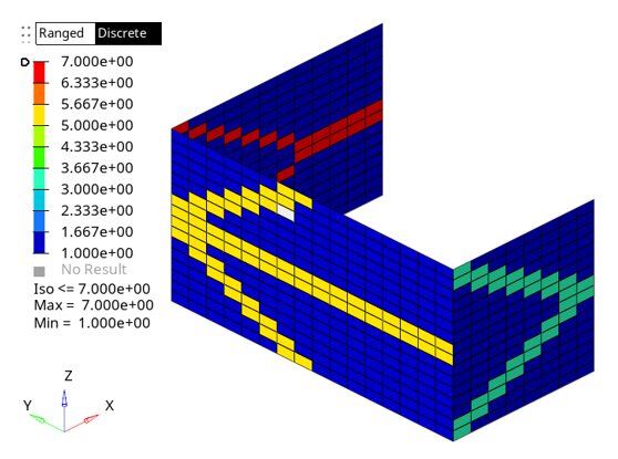
The effect of relocation with MIRROR can be seen in Figure 11(a) where the thicknesses have been mapped correctly.