
Cyclic Symmetry Analysis
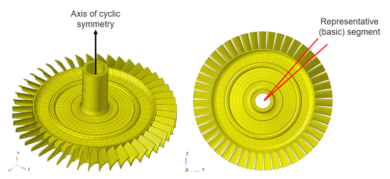
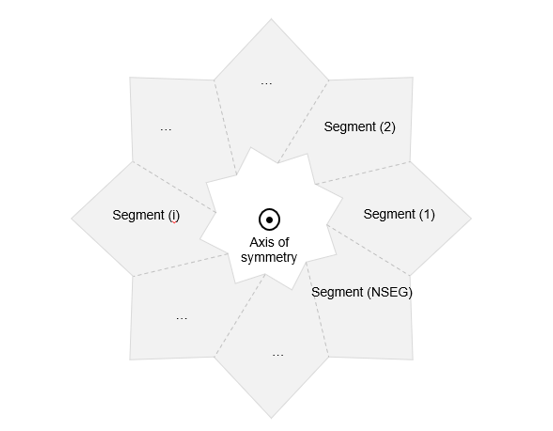
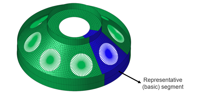
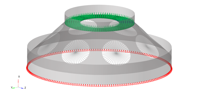
Cyclic symmetry is a type of symmetry in which a representative (or basic) segment, if patterned circularly about an axis of symmetry would result in the full model.
Structures with symmetry can often be modeled with one representative entity, from which the full structure can be obtained after certain operations (pattern, mirror, rotation, etc.). Such methods can lead to huge savings in modeling effort, computational time, and file storage. Therefore, exploiting symmetry in finite element models could prove to be very advantageous.
- The basic segment could either be the smallest repeating unit in the model or could involve several repeating units.
- Depending on your requirements, a full 360 degree model or a partial (as in, 270 degrees) model could be analyzed by suitably specifying the number of segments in the model definition.
In OptiStruct
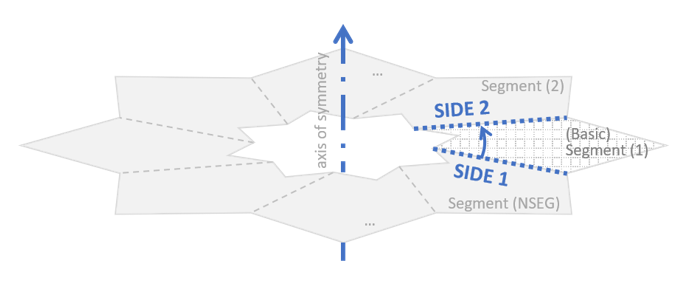
In a cyclic symmetry analysis, the boundaries on either side of the modeled base segment which are to be connected to adjacent segments are defined as SIDE 1 and 2. The direction of the axis of symmetry are determined using the right-hand thumb rule.
In cyclic symmetry analysis, the solution is internally decomposed as a series of harmonic solutions represented using harmonic indices, and they can be requested by the HARMONICS I/O Option.
The harmonic indices are supposed to be non-negative and must be no greater than (NSEG is the number of segments of the actual structure).
If NSEG is odd:
If NSEG is even:
| Subcase Type | Non-cyclic Symmetric Behavior | Cyclic Symmetric Behavior* |
|---|---|---|
| Linear Static |
|
|
| Normal Mode |
|
|
| Nonlinear Static, Nonlinear Transient | N/A |
|
| Preloading/Preloaded Subcase in Prestressed Analyses |
|
|
| Entry | Purpose | Additional Details |
|---|---|---|
| HARMONICS | Specifies the solution harmonics to be used. |
|
| NOUTPUT | Specifies the segments for which results must be recovered and output. |
|
| Entry | Purpose | Additional Details |
|---|---|---|
| CYAX | Specifies the grids that lie on the axis of symmetry. | This entry is optional for cyclic symmetry analysis. |
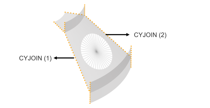
| CYJOIN | Specifies grid points on the segment boundaries that connect to adjacent segments. |
|
| CYSYM | Specifies the number of segments in the model. | This entry is mandatory for cyclic symmetry analysis. |
| LOADCYH | Specifies the loading by harmonics for linear static analysis. |
|
| LOADCYN | Defines the loading by segments for linear static analysis. |
|
| LOAD(ADD) | Defines the loading for implicit nonlinear analyses. |
|
Support Information
| Category | Supported Entities | Additional Details |
|---|---|---|
| Analysis type | Linear static analysis | |
| Normal modes analysis |
|
|
| Implicit nonlinear analyses |
|
|
| Prestressed analysis |
|
|
| Analysis output | DISPLACEMENT STRESS STRAIN Velocity/Acceleration Plasticity related results Contact results SPCF |
|
| Elements | CBEAM CTRIA3, CTRIA6 CQUAD4, CQUAD8 CTETRA, CHEXA, CPENTA CPYRA |
|
| Constraints | SPC MPC RBE2 RBE3 |
RBE2 and RBE3 will be generated only for the base segment in the result plot. |
| Materials | MAT1 MAT2 MAT9 MATT1 MATT2 MATT9 |
|
| Loads | SPCD Forces Pressures GRAV RFORCE TEMP |
|
Problem Setup
$ *************************************************************
$ EXAMPLE TO DEMONSTRATE A CYCLIC SYMMETRIC ANALYSIS SETUP
$ *************************************************************
.
.
NOUTPUT     = ALL
SUBCASE      101
  SPC   =  1
  LOAD  = 14

SUBCASE      102
  SPC  =  1
  METHOD(STRUCTURE) = 2
  HARMONICS   = 102

BEGIN BULK
$--1---><---2--><---3--><---4--><--5---><--6---><---7--><--8---><---9-->
CORD2C        11       0     0.0     0.0     0.0     0.0     0.0     1.0
+            1.0     0.0     0.0

EIGRL          2     0.0              50                             MAX

SET          102    MODE
+              0       1
CYSYM          4
CYJOIN         1              12    THRU      20
CYJOIN         2              22    THRU      30
GRID …
…

FORCE         51      12      11     1.0     0.0   100.0     1.0

LOADCYN       14     0.1       2             1.0      51
LOADCYN       14     0.1       4             1.0      51


.
.
Example
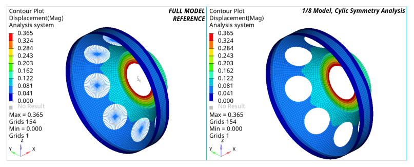
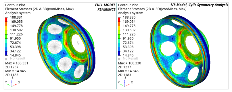
View Results in Cyclic Symmetry Analysis
Systems referenced by the CD field of grid points in the basic segment (including the basic coordinate system when CD is blank) is cyclically patterned and assigned to corresponding grids in each segment requested by NOUTPUT. This can also be used for viewing the results for each segment in its local coordinate system.
To view results in the basic coordinate system, The “Global coordinate system” option can be selected in HyperView.
Comments
- HyperMesh support for cyclic symmetry analysis would be available in future releases.