OS-T: 1550 Rubber Ring: Crush and Slide Using Self-Contact
This tutorial demonstrates self-contact which is used in this nonlinear large displacement implicit analysis using hyperelastic material and contacts in OptiStruct.
Before you begin, copy the file(s) used in this tutorial to your
working directory.
The following steps are included:
- Import the model into HyperMesh
- Set up hyperelastic material and self-contact.
- Set up nonlinear analysis
- View the results in HyperView
Launch HyperMesh and Set the OptiStruct User Profile
-
Launch HyperMesh.
The User Profile dialog opens.
-
Select OptiStruct and click
OK.
This loads the user profile. It includes the appropriate template, macro menu, and import reader, paring down the functionality of HyperMesh to what is relevant for generating models for OptiStruct.
Open the Model
- Click .
- Select the Rubber_ring_input.hm file you saved to your working directory.
-
Click Open.
The Rubber_ring_input.hm database is loaded into the current HyperMesh session, replacing any existing data.
Set Up the Model
Create the Material
- In the Model Browser, right-click and select from the context menu.
-
For Name, enter hyper_elastic.
A new material, hyper_elastic has beeen created.
- For Card Image, select MATHE.
- For MODEL, select ABOYCE.
-
Enter the material values next to the corresponding fields.
- For NU (Poisson's Ratio), enter 0.495.
- For RHO, enter 1.11e-9.
- For TEXP, enter 0.000165.
Figure 2. Define hyperelastic material 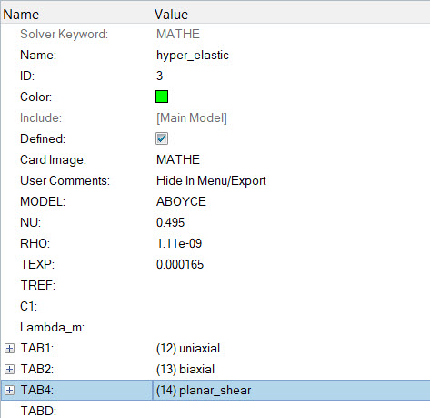
- Click TAB1 and assign Tension-Compression uniaxial.
- Click TAB2 and assign Equi-Biaxial Tension biaxial.
- Click TAB4 and assign Pure Shear planar_shear.
Create the Properties
-
In the Model Browser, right-click and select from the context menu.
A default PSHELL property displays in the Entity Editor.
- For Name, enter hyper_elastic.
- For Card Image, select PLSOLID.
- For Material, click .
-
In the Select Material dialog, select
hyper_elastic and click
OK.
Figure 3. Select material hyper_elastic for the -roperty 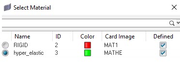
-
In the Model Browser, click on the component
WHEEL.
The component fields display in the Entity Editor.
- For Property, click .
-
In the Select Property dialog, select
hyper_elastic and click
OK.
The component WHEEL has been updated with a property of the same name and is currently the “Current Component” (see the box in the lower right for WHEEL). The material hyper_elastic is referenced by this component.
Figure 4. Select property hyper_elastic for the component 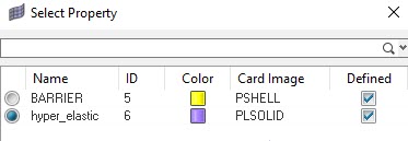
Create Properties for Contact Parameters
In this step, the properties for both surface to surface and self-contact surfaces will be defined.
- In the Model Browser, right-click and select from the context menu.
- For Name, enter Contact.
- For Card Image, select PCONT.
- Activate GPAD_OPT and for GPAD, select NONE from the drop-down menu.
- For STIFF, select HARD.
-
For MU1, enter 0.3.
Figure 5. Property values for Contact 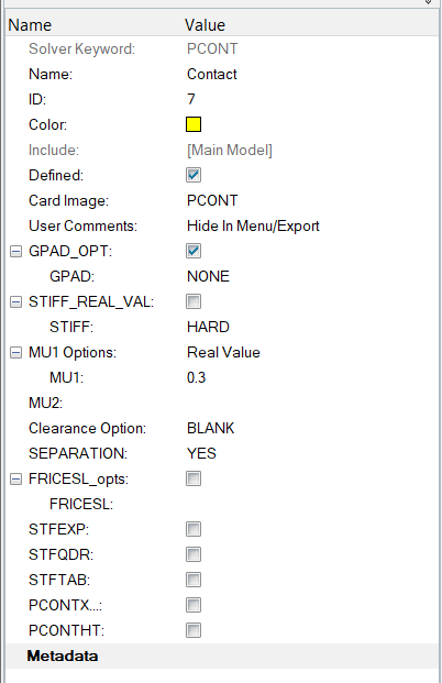
- In the Model Browser, right-click and select from the context menu.
- For Name, enter self_contact.
- For Card Image, select PCONT.
- Activate GPAD_OPT and for GPAD, select None from the drop-down menu.
- For STIFF, select AUTO.
- For MU1, enter 0.3.
Create Set Segments
The set segments will be defined, which will be used later to define the contact groups.
- In the Model Browser, right-click and select from the context menu.
- For Name, enter Top.
- Right-click on the component Top and select Isolate Only.
-
Click Entity IDs to select the elements corresponding to
Top.
Note: Make sure to switch the selection panel from faces to elements.
-
Click elems.
The selection panel opens.
- Select add shell faces from the drop-down menu,
- From the second drop-down, select elems as shown below.
-
Click .
This selects all the elements corresponding to the component Top.
Figure 6. Elements selection panel 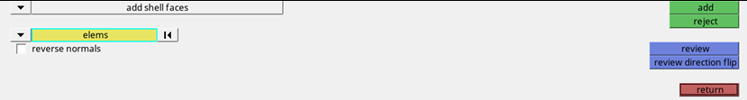
-
This creates a Top set segment with elements corresponding to the
Top.
Figure 7. Create Top set segment 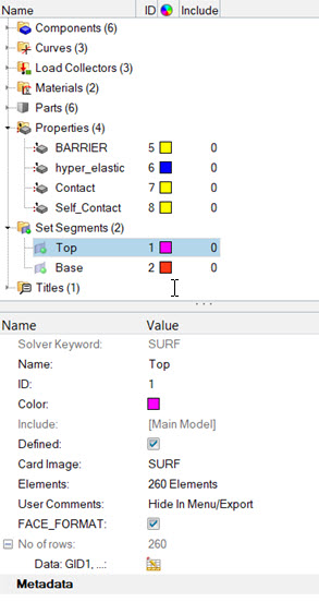
-
Similarly, create a set segment for the component
Base.
Note: Make sure to select FACE_FORMAT, while creating the set segment for Top and Base.
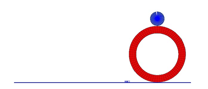
- To create a contact set segment for the inner and outer surface of the wheel, right-click on the component Wheel, select Isolate Only.
- In the Model Browser, right-click and select from the context menu.
- For Name, enter rubber_inner.
-
Set the selection panel to add solid faces.
Figure 8. Create rubber_inner contact set segment 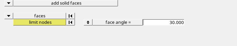
-
Select the inner surface of the wheel to select the elements contributing to
the Rubber_inner set segment.
Figure 9. Select rubber_inner contact set segment 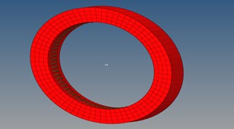
- Similarly, create a contact set segment Rubber_outer by selecting the outer face of the component Wheel.
Create Contact Groups
Here the contact groups will be defined.
- In the Model Browser, right-click and select from the context menu.
- For Name, enter Top_rubber.
- For Card Image, select CONTACT.
- For Property Option, select Property Id.
-
Expand PID and select Contact
surfaces.
Figure 10. Create a Contact Group 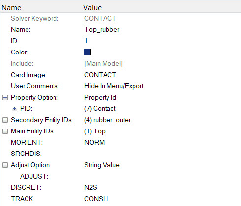
- For Secondary Entity IDs, select rubber_outer.
- For Main Entity IDs, select Top.
- For MORIENT (Contact Orientation), select NORM.
- For DISCR, select N2S (Node to Surface).
- For TRACK, select CONSLI.
- Similarly, create a contact group Bottom_rubber with rubber_outer as the Secondary Entity IDs and Base as Main Entity IDs with other parameters being the same from Figure 10.
- Now, create a contact group Self_contact and select the Card image to CONTACT.
- For Property Id, assign the self_contact property created previously, as shown in Figure 11.
- Select the set segment created earlier for the Rubber_inner as the Secondary Entity IDs.
-
For DISCRET, select S2S (Surface to Surface).
Figure 11. Create a self_contact Group 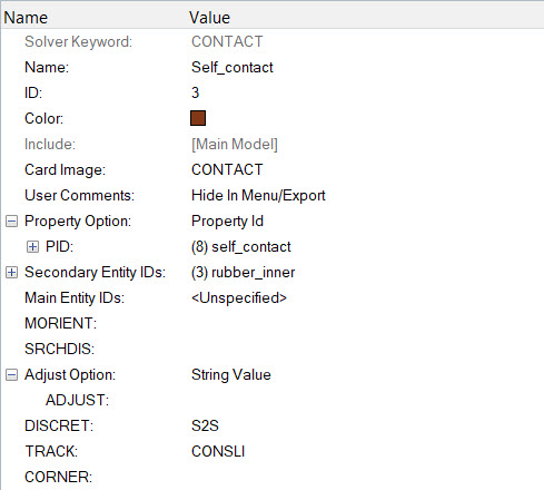
Apply Loads and Boundary Conditions
In the following steps, you will apply the boundary conditions and prescribed displacement on the model.
Create SPC Load Collector
-
In the Model Browser, right-click and select from the context menu.
A default load collector displays in the Entity Editor.
- For Name, enter spc_top1.
- Click to open the Constraints panel.
- Select the node 2269 corresponding to the Top component.
-
Constrain the node in 1, 3,
4, 5, and
6 directions.
Assigns the boundary conditions for the first load step (Compression).
Figure 12. Constrain Node 2269 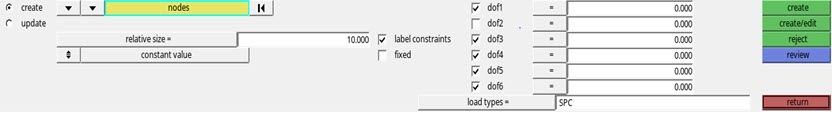
-
Click create.
This applies the constraints to the selected nodes.
-
Constrain the dof2, enter -6.44.
Assigned a displacement of magnitude in the negative y-direction.
Figure 13. Apply Displacement to the Node 2269 Corresponding to First Load Step 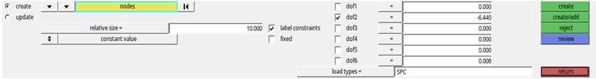
- In the Model Browser, right-click and select from the context menu.
- For Name, enter spc_top2.
- Apply the constrains in the dof's 3, 4, and 5.
-
For dof1, enter -13.0.
Applies a displacement of magnitude in the negative x-direction.
-
For dof2, enter -6.44.
Applies a displacement of magnitude in the negative y-direction corresponding to the x and y displacement of the ring.
-
For dof6, enter -10.44.
Applies a rotation in the x-z plane.
Figure 14. Apply Displacement to the Node 2269 Corresponding to the Second Load Step 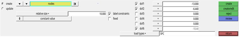
- In the Model Browser, right-click and select from the context menu.
- For Name, enter SPC_base_wheel.
- Right-click on the component Wheel and select Isolate Only.
- Click to open the Constraints panel.
-
Click nodes and from the panel, select
displayed and constrain
dof3.
Figure 15. Apply Constraints to the Wheel 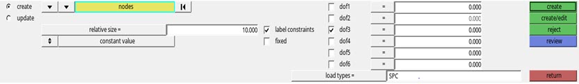
- In the Model Browser, right-click and select from the context menu.
- For Name, enter SPC_base_wheel_X.
-
Constrain the line of nodes on the front face, as shown in Figure 16 in the x direction (dof1) and also
constrain the node 2266 in all dofs.
Figure 16. 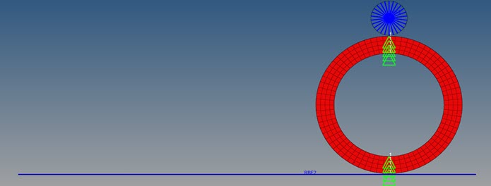
- In the Model Browser, right-click and select from the context menu.
- For Name, enter SPC_base.
- On the constraint panel, constrain node 2266 in all dofs.
- In the Model Browser, right-click and select from the context menu.
- For Name, enter SPCADD1.
- For Card Image, select SPCADD.
- For SPCADD_Num_Set, enter 3.
-
Define the cards spc_top1,
SPC_base_wheel and
SPC_wheel_base_X.
The SPCADD card is created.
Figure 17. Create SPCADD Card 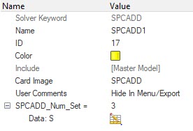
- In the Model Browser, right-click and select from the context menu.
- For Name, enter SPCADD2.
- Define the cards spc_top2, SPC_wheel_base and SPC_base as explained above.
Create NLPARM Load Step Input
- In the Model Browser, right-click and select .
- For Name, enter NLPARM.
- Click Color and select a color from the color palette.
-
For Config type, select Nonlinear Parameters.
Type default is NLPARM.
- For NINC, enter 2000.
- For MAXITER, enter 25.
- For CONV, select UPW.
- For EPSU, enter 0.001.
- For EPSP, enter 0.001.
- For EPSW, enter 1e-11.
Create NLADAPT Load Step Input
- In the Model Browser, right-click and select .
- For Name, enter NLADAPT1.
- For Config type, select Time step Parameters.
- For Type, the default is NLADAPT.
- For DTMAX, enter 0.1.
-
For DTMIN, enter 1e-6.
Figure 18. Create NLADAPT load step input 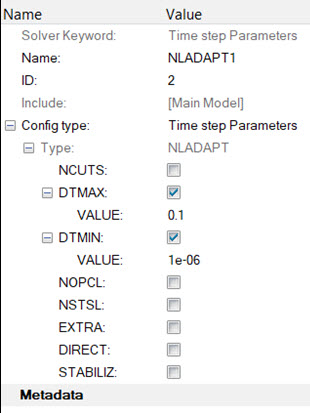
- In the Model Browser, right-click and select .
- For Name, enter NLADAPT2.
- For DTMAX, enter 0.025.
- For DTMIN, enter 1e-6.
Create CNTSTB Load Collector
-
In the Model Browser, right-click and select from the context menu.
A default load collector displays in the Entity Editor.
- For Name, enter CNTSTB.
- For SI, enter 1e-5
- For SCALE, enter 1.
-
For TFRAC, enter 0.1.
Figure 19. Create a CNTSTB Card 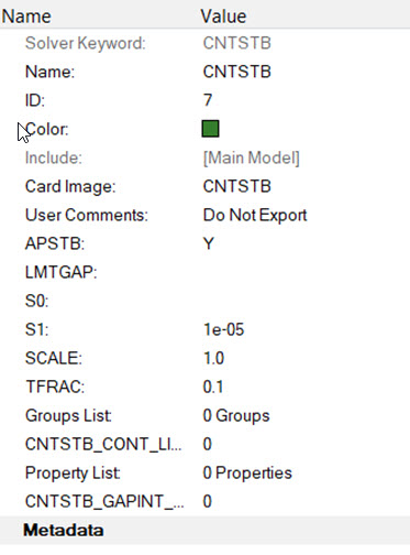
Create NLOUT Load Step Input
- In the Model Browser, right-click and select .
- For Name, enter NLOUT.
- For Config type, select Output Parameters.
- For Type, the default is NLOUT.
- For NINT, enter 500.
-
Activate SVNONCNV.
Figure 20. Create NLOUT Card 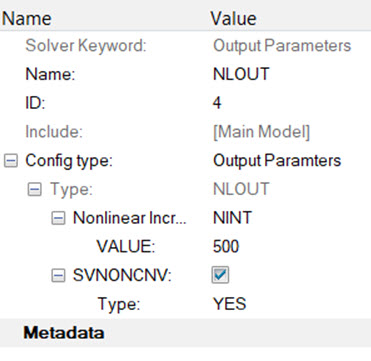
Define Output Control Parameters
- In the Model Browser, right-click and select .
-
Below DISPLACEMENT, ELFORCE, STRESS and CONTF, set Option to
Yes.
Figure 21. 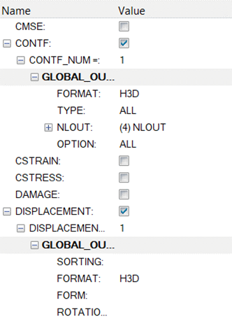
Activate PARAM Control Cards
- From the Anaysis page, select Control Cards.
- For Control Cards, select PARAM.
- Activate HASHASSM, enter YES.
- Activate LGDISP, enter 1.
- Activate NLMON, enter DISP.
-
Activate UNSYMSLV, enter
YES.
Figure 22. Create Control Card 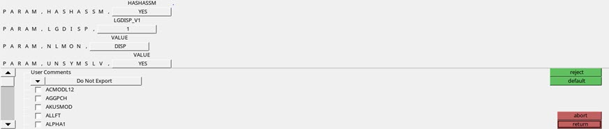
Activate GLOBAL_CASE_CONTROL
- From the Analysis page, select control cards.
-
For control cards, select CNTNLSUB and select
YES.
Figure 23. Create Global Case Control 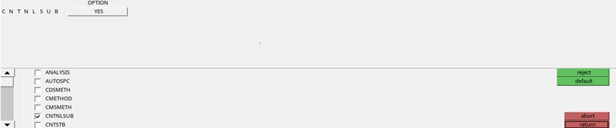
Create Load Steps
-
In the Model Browser, right-click and select .
A default load collector displays in the Entity Editor
- For Name, enter RING_DOWN.
- For Type, select Nonlinear Static.
-
In the SPC Select Loadcol dialog, select
SPCADD1 from the list of load collectors and click
OK.
This selects the boundary conditions created above.
- Similarly select the NLPARM, NLADAPT1, NLOUT, and CNTSTB and assign respective load step inputs and load collectors.
- In the Model Browser, right-click and select .
- For Name, enter Ring_down2.
- For Type, select Nonlinear Static.
- In the SPC Select Loadcol dialog, select SPCADD2 from the list of load collectors and click OK.
- Similarly, select the NLPARM, NLADAPT2, NLOUT, and CNTSTB and assign respective load step inputs and load collectors.
Submit the Job
-
From the Analysis page, click the OptiStruct
panel.
Figure 24. Accessing the OptiStruct Panel 
- Click save as.
- In the Save As dialog, specify location to write the OptiStruct model file and enter for filename.
-
Click Save.
The input file field displays the filename and location specified in the Save As dialog.
- Set the export options toggle to all.
- Set the run options toggle to analysis.
- Click OptiStruct to submit the job.
View the Results
- Once you receive the message Process completed successfully in the command window, click HyperView.
- Open the results and plot the displacement and the von Mises stress contour at 100% load.
-
On the toolbar, click
 (Contour).
- Under Result type, from the first drop-down menu, select Element Stresses (2D & 3D)(t).
-
Under Result type, from the second drop-down menu, select
vonMises.
Figure 25. Contour Panel 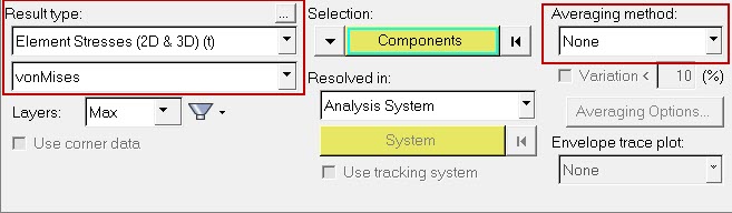
- Verify that the fields in the Contour panel match those in Figure 25 and click Apply.
-
Similarly, in the menu below Result type, select
Displacement from the first drop-down menu and
Mag from the second drop-down menu.
Figure 26. Displacement Result for First Load Step 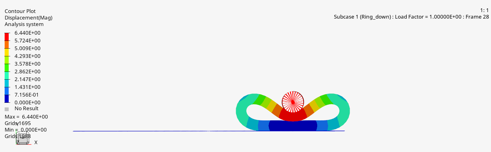
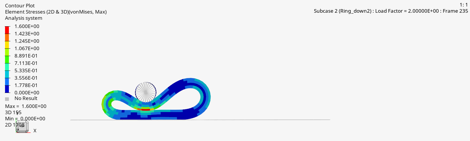
Figure 27. Stress Result for First Load Step 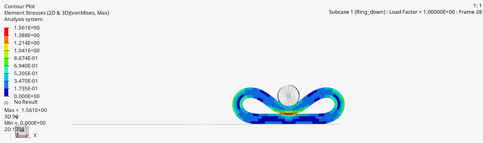
Figure 28. Displacement Result for Second Load Step 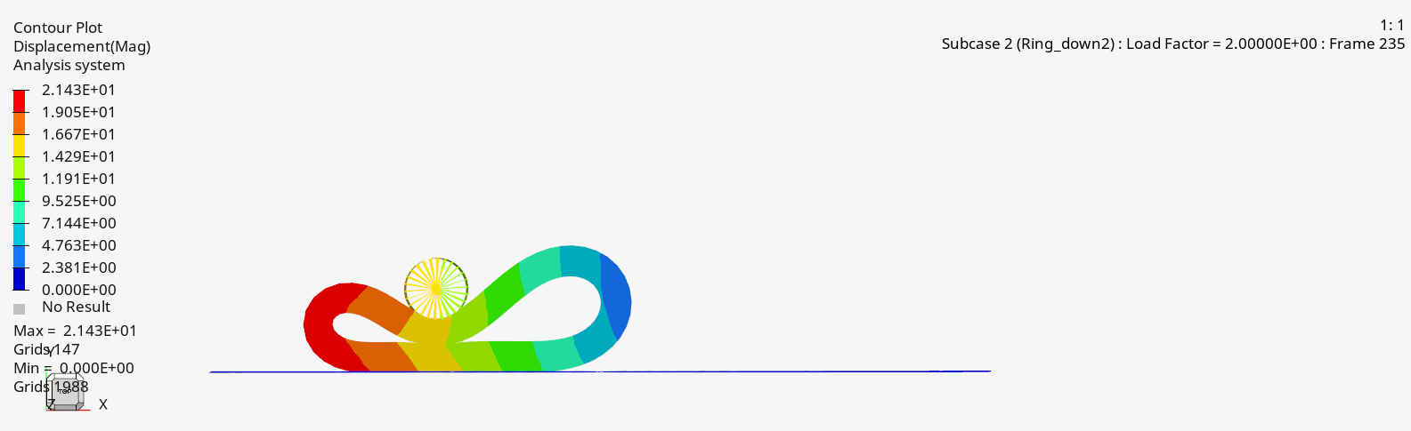
Figure 29. Stress Result for Second Load Step