OS-T: 1570 Nonlinear Transient Analysis of Crank Slider
In this tutorial, an existing finite element model of a slider crank is used to demonstrate how to perform Nonlinear Transient Analysis using OptiStruct.
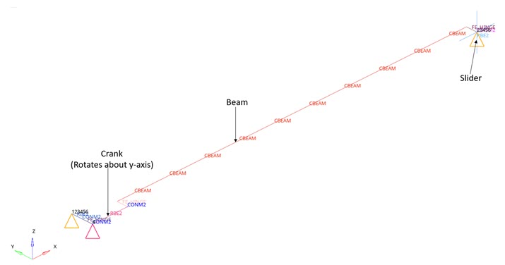
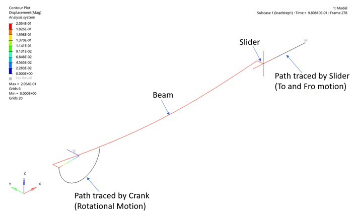
Figure 1 illustrates the structural model used for this tutorial: A slider crank is a four-link mechanism with three revolute joints and one sliding joint. The mechanism is completely constrained at one end and transient load are applied to the crank. The Nonlinear transient analysis is run for a total time of 1 second with the time being divided into 200 increments (that is step time equal to 0.005). A concentrated mass is defined at the center of the slider, both the ends of the crank and at the hinge.
You will be simulating the Slider Crank model, which is modeled using beam/solid elements. The crank will be rotated by 180 degrees about the z-axis by applying appropriate constraints on other links.
- One with beam elements
- One with solid elements
Launch HyperMesh and Set the OptiStruct User Profile
-
Launch HyperMesh.
The User Profile dialog opens.
-
Select OptiStruct and click
OK.
This loads the user profile. It includes the appropriate template, macro menu, and import reader, paring down the functionality of HyperMesh to what is relevant for generating models for OptiStruct.
Import the Model
-
Click .
An Import tab is added to your tab menu.
- Select the crank_slider.fem file you saved to your working directory.
- Click Import, then click Close to close the Import tab.
Set Up the Model
Create the Material
Here you will define the beam material.
- In the Model Browser, right-click and select from the context menu.
-
For Name, enter material1.
A new material, material1 has beeen created.
- Click Color and select a color from the color palette.
- For Card Image, select MAT1.
- For E, enter 200000000.
- For N, enter 0.3.
- For RHO, enter 7200.
Create the Property
Here you will create the beam property.
- In the Model Browser, right-click and select from the context menu.
- For Name, enter property1.
- Click Color and select a color from the color palette.
- For Card Image, select PBEAM and click Yes to confirm.
- For Material, click .
- In the Select Material dialog, select material1 and click OK.
- For Beam Section, click .
- In the Select Beamsection dialog, select rectangle section 2 from the list and click OK.
- In the Model Browser, click the component BEAM.
-
Under property window for BEAM, for Property, select
property1 that you created.
The Material option is auto-filled.
Apply Loads and Boundary Conditions
Create TABLED1 Curve
- In the Model Browser, right-click and select .
- For Name, enter TABLED1.
- For Card Image, select TABLED1 from the drop-down menu.
-
In the Model Browser, right-click on the
TABLED1 curve and select Edit
enter the values:
Figure 2. 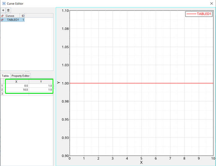
-
Click Close.
The curve TABLED1 that defines the time history of the loading has been created.
Create TSTEP Load Collector
Here you will define the hyper elastic behavior of the implant.
- In the Model Browser, right-click and select .
-
For Name, enter tstep.
- Click Color and select a color from the color palette.
- For Card Image, select TSTEP from the drop-down menu.
- For TSTEP_NUM, enter 1 and press Enter.
- For N, enter the number of time steps as 200.
- For DT, enter the time increment of 0.005.
- Click Close.
Create SPC Load Collector
- In the Model Browser, right-click and select .
- For Name, enter spc.
- Click Color and select a color from the color palette.
- For Card Image, select NONE.
- Click to open the Constraints panel.
- Click nodes, then select the hinge node (Figure 3).
- Check all Degrees of Freedom (DoFs) and enter 0 for each DoF.
- For load types=, select SPC.
-
Click create.
Figure 3. Constraints on the hinge node 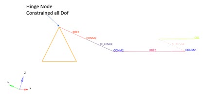
-
Select the center node of the slider (Figure 4) and check all DoFs; except DoF1.
This indicates that DoF1 is the only active Degree of Freedom.
Figure 4. Constraints applied to the center node of the slider 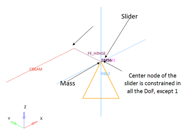
-
Click create and return.
The 2 nodes are constrained in one load collector.
Create SPC1 Load Collector
One more SPC load collector is created here.
- In the Model Browser, right-click and select .
- For Name, enter spc1.
- Click Color and select a color from the color palette.
- For Card Image, select NONE.
- Click to open the Constraints panel.
- Select the first node of crank (Figure 5).
-
Check all Degrees of Freedom (DoFs); except DoF4.
This indicates that DoF4 is the only active Degree of Freedom.
Figure 5. Constraints applied to the first node of the crank 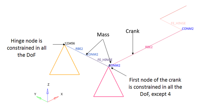
- For load types=, select SPC.
- Click create and return.
Create SPCD Load Collector
- In the Model Browser, right-click and select .
- For Name, enter spcd.
- Click Color and select a color from the color palette.
- For Card Image, select NONE.
- Click to open the Constraints panel.
- Select the first node of crank.
- Check all Degrees of Freedom (DoFs); except dof4 and enter a value of 0 against each checked DoF.
-
For DoF4, enter the value 3.14.
This indicates that DoF4 is the only active Degree of Freedom.
- For load types=, select SPCD.
- Click create and return.
Create SPCADD Load Collector
- In the Model Browser, right-click and select .
- For Name, enter spcadd.
- Click Color and select a color from the color palette.
- For Card Image, select SPCADD.
- For SPCADD_Num_Set, enter 2.
-
Click on the Table icon
 next to the Data
field and enter the following values in the pop-out window as:
next to the Data
field and enter the following values in the pop-out window as:
Figure 6. 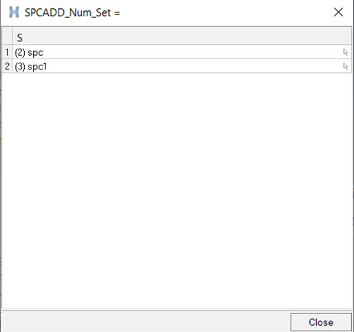
Create GRAV Load Collector
- In the Model Browser, right-click and select .
- For Name, enter grav.
- Click Color and select a color from the color palette.
- For Card Image, select GRAV from the drop-down menu.
- For G, enter 9.8.
- For N3, enter -1.0.
Create a TLOAD Load Step Input
- In the Model Browser, right-click and select .
- For Name, enter tload.
- For Config type, select Dynamic Load – Time Dependent from the drop-down list
- For Type, select TLOAD1 from the drop-down menu.
- For Exciteid , click .
- In the Select Loadcol dialog, select spcd from the list of load collectors.
- For Type, select VELO.
- For TID, select TABLED1 curve.
Create tload_grav Load Step Input
Here you will create one more TLOAD load step input.
- In the Model Browser, right-click and select .
- For Name, enter tload_grav.
- For Config type, select Dynamic Load - Time Dependent from the drop-down menu.
- For Type, select TLOAD1 from the drop-down menu.
- For EXCITED, click .
- In the Select Loadcol dialog, select grav from the list of load collectors.
- For TYPE, select LOAD.
- For TID, select TABLED1 curve.
Create a DLOAD Load Step Input
- In the Model Browser, right-click and select .
- For Name, enter dload.
- For Config type, select Dynamic Load Combination from the drop-down menu.
- For Type, the default is DLOAD.
- For S (scale factor), enter 1.0.
- For DLOAD_NUM, enter 2.
- For data, select tload and tload_grav and enter 1 as the scale factor for both loads.
- Click Close.
Create NLPARM Load Step Input
The nonlinear implicit parameters are defined.
- In the Model Browser, right-click and select .
- For Name, enter nlparm.
- For Config type, select Nonlinear Parameters from the drop-down menu.
- For Type, the default is NLPARM.
- For NINC, enter 200.
- For DT, enter 0.005.
Create NLADAPT Load Step Input
- In the Model Browser, right-click and select .
- For Name, enter nladapt.
- For Config type, select Time step Parameters.
- For Type, the default is NLADAPT.
- For DTMAX, enter 0.005.
- For DTMIN, enter 1e-05.
- For NCUTS, enter 5.
Create NLMON Load Step Input
- In the Model Browser, right-click and select .
- For Name, enter nlmon.
- For Config type, select Runtime Monitoring from the drop-down menu.
- For Type, the default is NLMON.
- For ITEM, select DISP.
- For INT, select ITER.
Create NLOUT Load Step Input
- In the Model Browser, right-click and select .
- For Name, enter NLOUT.
- For Config type, select Output Parameters.
- For Type, the default is NLOUT.
- For NINT, enter 200.
Create Load Steps
The nonlinear transient load step is created here.
-
In the Model Browser, right-click and select .
A default load step input displays in the Entity Editor.
- For Name, enter loadstep1.
- For Type, select Nonlinear transient from the drop-down menu.
- For SPC, select spcadd.
- For TSTEP, select tstep.
- For NLPARM(LGDISP), select nlparm.
- For DLOAD, select dload from the list of load step inputs.
- For NLADAPT, select NLAdapt from the list of load step input.
- For NLOUT, select NLout.
- Under SUBCASE OPTION, toggle ANALYSIS, and select TYPE DTRAN.
- Activate NLMON and select nlmon.
Define Output Control Parameters
- From the Analysis page, select control cards.
- Click on GLOBAL_OUTPUT_REQUEST.
- Below DISPLACEMENT, set Option to Yes and select H3D for Output format.
- For Format, select PLOT.
- Click return twice to go to the main menu.
Submit the Job
-
From the Analysis page, click the OptiStruct
panel.
Figure 7. Accessing the OptiStruct Panel 
- Click save as.
- In the Save As dialog, specify location to write the OptiStruct model file and enter crank_slider.fem for filename.
-
Click Save.
The input file field displays the filename and location specified in the Save As dialog.
- Set the export options toggle to all.
- Set the run options toggle to analysis.
- Set the memory options toggle to memory default.
-
Click OptiStruct to submit
the job.
If the job is successful, new results files should be in the directory where the crank_slider.fem was written. The crank_slider.out file is a good place to look for error messages that could help debug the input deck if any errors are present.The default files written to the directory are:
- slider_crank.html
- HTML report of the analysis, providing a summary of the problem formulation and the analysis results.
- slider_crank.out
- ASCII based output file of the model check run before the simulation begins and gives nonlinear iteration history, as well as basic information on the results of the run.
- slider_crank.h3d
- HyperView compressed binary results file.
- slider_crank.stat
- Summary, providing CPU information for each step during analysis process.
View the Results
- Once you receive the message Process completed successfully in the command window, click HyperView.
- Open the results and plot the displacement and the von Mises stress contour at 100% load.
-
On the toolbar, click
 (Contour).
- Under Result type, from the first drop-down menu, select Element Stresses (2D & 3D)(t).
-
Under Result type, from the second drop-down menu, select
vonMises.
Figure 8. Contour Panel 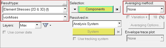
-
Verify that the fields in the Contour panel match those in
Figure 8 and click
Apply.
Figure 9. Contour of Displacement in Crank Slider model. Time = 0.98 sec