OptiStruct
OptiStruct

2022.2

  1. Home
  2. Tutorials

    Discover OptiStruct functionality with interactive tutorials.

  3. HyperMesh Tutorials

    Tutorials using HyperMesh.

  4. Basic Small Displacement Finite Element Analysis
  5. OS-T: 1110 Modal Analysis Setup

    In this tutorial, you continue to gain an understanding of the basic concepts for creating a OptiStruct input file. More specifically, learn how to set up a model for modal analysis, specify solver specific controls and also submit an input file to the solver from HyperMesh.

  • What's New
  • Overview
  • Tutorials
  • User Guide
  • Reference Guide
  • Example Guide
  • Verification Problems
  • Frequently Asked Questions
Index
OptiStruct

2022.2

OptiStruct
  • What's New

    View new features for OptiStruct 2022.2.

  • Overview

    OptiStruct is a proven, modern structural solver with comprehensive, accurate and scalable solutions for linear and nonlinear analyses across statics and dynamics, vibrations, acoustics, fatigue, heat transfer, and multiphysics disciplines.

  • Tutorials

    Discover OptiStruct functionality with interactive tutorials.

    • Run OptiStruct at the Command Line
    • HyperMesh Tutorials

      Tutorials using HyperMesh.

      • Run OptiStruct from HyperMesh
      • Basic Small Displacement Finite Element Analysis
        • OS-T: 1000 Linear Static Analysis of a Plate with a Hole

          This tutorial demonstrates the creation of finite elements on a given CAD geometry of a plate with a hole. Further, application of boundary conditions and a finite element analysis of the problem are explained. Post-processing tools are used in HyperView to determine deformation and stress characteristics of the loaded plate.

        • OS-T: 1010 Thermal Stress Analysis of a Coffee Pot Lid

          In this tutorial, an existing finite element model of a plastic coffee pot lid demonstrates how to apply constraints and perform an OptiStruct finite element analysis. HyperView post-processing tools are used to determine deformation and stress characteristics of the lid.

        • OS-T: 1020 Normal Modes Analysis of a Splash Shield

          In this tutorial, an existing finite element model of an automotive splash shield is used to demonstrate how to set up and perform a normal modes analysis. HyperView post-processing tools are used to determine mode shapes of the model.

        • OS-T: 1030 3D Inertia Relief Analysis

          An existing finite element model is used in this tutorial to demonstrate how HyperMesh may be used to set-up an inertia relief analysis. The analysis is then performed using OptiStruct and post-processed in HyperView.

        • OS-T: 1040 3D Buckling Analysis

          In this tutorial the steps required to perform a buckling analysis using OptiStruct are covered.

        • OS-T: 1050 Connection of Dissimilar Meshes using CWELD Elements

          In this tutorial, an existing finite element model of a simple cantilever beam is used to demonstrate how to connect dissimilar meshes using CWELD elements.

        • OS-T: 1060 Analysis of a Composite Aircraft Structure using PCOMPG

          This tutorial takes you through the process of developing a ply lay-up definition for a composite structure using a PCOMPG card, and shows the advantages of post-processing the results with global ply numbers. The traditional definition method, using PCOMP, is introduced first here to ultimately show the practical advantages of using PCOMPG for the given scenario.

        • OS-T: 1070 Analysis of an Axi-symmetric Structure

          In this tutorial the method of modeling an axi-symmetry problem in OptiStruct is covered.

        • OS-T: 1080 Coupled Linear Heat Transfer/Structure Analysis

          A coupled heat transfer/structure analysis on a steel pipe is performed in this tutorial.

        • OS-T: 1085 Linear Steady-state Heat Convection Analysis

          This tutorial performs a heat transfer analysis on a steel pipe.

        • OS-T: 1090: Linear Transient Heat Transfer Analysis of an Extended Surface Heat Transfer Fin

          This tutorial outlines the procedure to perform a linear transient heat transfer analysis on a steel extended-surface heat transfer fin attached to the outer surface of a system generating heat flux (Example: IC engine).

        • OS-T: 1100 Thermal Stress Analysis of a Printed Circuit Board with Anisotropic Material Properties

          Printed Circuit Boards (PCB's) are used in electronic components to both mechanically support and provide electrical connections between components. Construction involves etching a thin copper layer that has been deposited onto a non-conductive, glass-fiber/epoxy composite substrate. Electrical components are then mounted to the board and connected to the copper traces with electrical solder.

        • OS-T: 1110 Modal Analysis Setup

          In this tutorial, you continue to gain an understanding of the basic concepts for creating a OptiStruct input file. More specifically, learn how to set up a model for modal analysis, specify solver specific controls and also submit an input file to the solver from HyperMesh.

        • OS-T: 1120 Linear Static Analysis using User-Defined Structural Material (MATUSR)

          This tutorial demonstrates how to use the MATUSR user-defined material for linear static analysis for solid (Phase 1) and shell (Phase 2) elements.

      • Advanced Small Displacement Finite Element Analysis
      • Large Displacement Finite Element Analysis
      • Fluid-Structure Interaction Analysis
      • Multibody Dynamics Analysis
      • Topology Optimization
      • Topography Optimization
      • Combination Optimization
      • Size Optimization
      • Shape Optimization
      • Fatigue Analysis
      • Nonlinear Explicit Analysis

        This section presents nonlinear explicit analysis examples generated using OptiStruct. Each example uses a problem description, execution procedures, and results to demonstrate how OptiStruct is used.

      • Aeroelastic Analysis

      • Third Party Interface

    • HyperWorks Tutorials

      Tutorials using HyperWorks.

    • SimLab Tutorials

      Video tutorials using SimLab.

  • User Guide

    This manual provides detailed information regarding the features, functionality, and simulation methods available in OptiStruct.

  • Reference Guide

    This manual provides a detailed list and usage information regarding input entries, output entries, and parameters available in OptiStruct.

  • Example Guide

    The OptiStruct Example Guide is a collection of solved examples for various solution sequences and optimization types and provides you with examples of the real-world applications and capabilities of OptiStruct.

  • Verification Problems

    This manual presents solved verification models including NAFEMS problems.

  • Frequently Asked Questions

    This section provides quick responses to typical and frequently asked questions regarding OptiStruct.

View All Altair Simulation Help

OptiStruct
OptiStruct

2022.2

  1. Home
  2. Tutorials

    Discover OptiStruct functionality with interactive tutorials.

  3. HyperMesh Tutorials

    Tutorials using HyperMesh.

  4. Basic Small Displacement Finite Element Analysis
  5. OS-T: 1110 Modal Analysis Setup

    In this tutorial, you continue to gain an understanding of the basic concepts for creating a OptiStruct input file. More specifically, learn how to set up a model for modal analysis, specify solver specific controls and also submit an input file to the solver from HyperMesh.

  • What's New
  • Overview
  • Tutorials
  • User Guide
  • Reference Guide
  • Example Guide
  • Verification Problems
  • Frequently Asked Questions
Index

OS-T: 1110 Modal Analysis Setup

In this tutorial, you continue to gain an understanding of the basic concepts for creating a OptiStruct input file. More specifically, learn how to set up a model for modal analysis, specify solver specific controls and also submit an input file to the solver from HyperMesh.

Before you begin, copy the file(s) used in this tutorial to your working directory.
  • channel_brkt_modal.hm
To complete the setup of the model for a modal analysis with OptiStruct, you need to define a normal modes SUBCASE, containing METHOD and SPC statements.

rd1110-01
Figure 1.

Launch HyperMesh and Set the OptiStruct User Profile

  1. Launch HyperMesh.
    The User Profile dialog opens.
  2. Select OptiStruct and click OK.
    This loads the user profile. It includes the appropriate template, macro menu, and import reader, paring down the functionality of HyperMesh to what is relevant for generating models for OptiStruct.

Open the Model

  1. Click File > Open > Model.
  2. Select the channel_brkt_modal.hm file you saved to your working directory.
  3. Click Open.
    The channel_brkt_modal.hm database is loaded into the current HyperMesh session, replacing any existing data.

Set Up the Model

Review and Edit the Materials

This step can be done from the Model Browser.
  1. In the Model Browser, expand the Material folder to show the two materials in the model.
  2. Click aluminum.
    The material entry is displayed in the Entity Editor.
  3. For RHO, enter 2.7e-9.
  4. Repeat steps 1 to 3 to input an RHO value of 7.9e-9 for the steel entry.

Create modal Load Step Input

This can be done using the Load Step Inputs panel and the create subpanel.

  1. In the Model Browser, right-click and select Create > Load Step Inputs.
  2. For Name, enter modal.
  3. Set Config type, select Real Eigen value extraction.
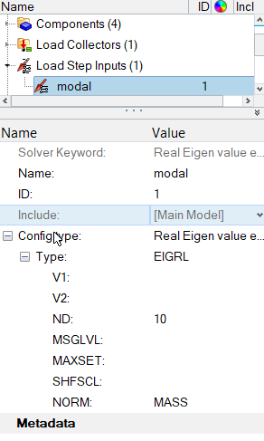
  4. For Type, select EIGRL.
  5. For ND, enter 10.
    ND specifies the number of modes to extract.

    os_1110_13_01
    Figure 2.

Create constraints Load Collector

  1. In the Model Browser, right-click and select Create > Load Collector.
  2. For Name, enter constraints.
  3. Set Card Image to None.

Apply Constraints (OptiStruct SPC) on the Channel

  1. Expand the Component folder in the Model Browser.
  2. Click the geometry icon entityGeometry-24 next to the channel component to turn the geometry display on.
  3. Click the Isometric View icon viewAxisOrientationIso-24 in the toolbar.
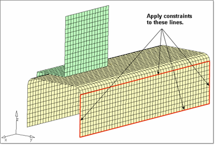
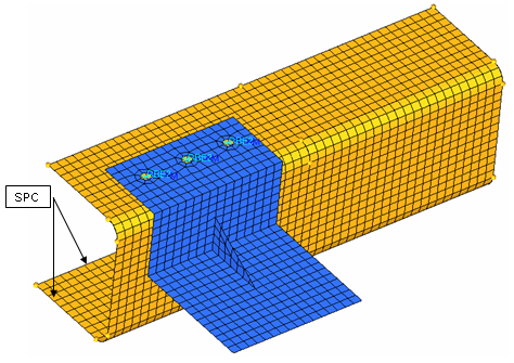
    You are going to create the SPC constraints on the nodes along the lines on the perimeter of the channel's bottom surface, as shown in the image below.

    rd1110-02
    Figure 3. Apply Constraints on the Channel
  4. Click BCs > Create > Constraints to open the Constraints panel.
  5. Switch the entity selector to lines.
  6. Select the six lines on the perimeter of the channel's bottom surface.
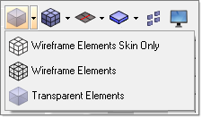
    To view the selected lines clearly, switch to Transparent Elements mode, as shown below:

    rd1110_transparent
    Figure 4.
  7. Activate degrees of freedom (DOF) 1 through 6.
    • DOFs with a check will be constrained while DOFs without a check will be free.
    • DOFs 1, 2, and 3 are x, y, and z translation degrees of freedom.
    • DOFs 4, 5, and 6 are x, y, and z rotational degrees of freedom.
  8. For size =, enter 10.
    The display size of the constraints is reduced.
  9. Click create > return to exit the panel.

Map the Constraints

Use the Load on Geom panel in this step.
  1. From the Analysis page, click load on geom.
  2. Click loadcols, and select constraints.
  3. Click select to complete the selection of load collectors.
  4. Click map loads.
    A constraint is at each node associated to the geometry lines.
  5. Click return to exit the panel.

Define the Load Step

Use the Load Step Entity Editor in this step. Define the loadstep to contain the load collectors constraints and modal.
  1. In the Model Browser, right-click and select Create > Load Step.
  2. For Name, enter normal_modes.
  3. For Analysis type, select Normal modes.
  4. For METHOD(STRUCT), select modal.
  5. For SPC, select the load collector constraints.

Define the Formats of Result Files

In the Control Cards panel, use the OUTPUT card to add two output requests for the Altair H3D and HyperMesh .res formats.
  1. Click Setup > Create > Control Cards to open the Control Cards panel.
  2. Click next to go to the next panel menu of control cards.
  3. Select the control card OUTPUT.
    Notice in the card image the one OUTPUT line is set to a default value. This specifies OptiStruct to output the results to a HyperMesh command file.
  4. Click the default value and select H3D from the pop-up menu.
  5. For number_of_outputs =, enter 2.
    A second OUTPUT line appears in the card image.
  6. Click the default value again and select HM for the second output type.
    This specifies OptiStruct to output results to a H3D file and a . res file, which can be viewed in HyperView Player. Also, an HTML report file is output and the H3D file is embedded in it.
  7. Click return to return to the Control Cards panel.
    Note: The OUTPUT button is green. This indicates the card is exported to the OptiStruct input file.
  8. Click return to exit the panel.

Submit the Job

  1. From the Analysis page, click the OptiStruct panel.

    OS_1000_13_17
    Figure 5. Accessing the OptiStruct Panel
  2. Click save as.
  3. In the Save As dialog, specify location to write the OptiStruct model file and enter modal_analysis for filename.
    For OptiStruct input decks, .fem is the recommended extension.
  4. Click Save.
    The input file field displays the filename and location specified in the Save As dialog.
  5. Set the export options toggle to all.
  6. Set the run options toggle to analysis.
  7. Set the memory options toggle to memory default.
  8. Click OptiStruct to launch the OptiStruct job.
If the job is successful, new results files should be in the directory where the modal_analysis.fem was written. The modal_analysis.out file is a good place to look for error messages that could help debug the input deck if any errors are present.

© 2022 Altair Engineering, Inc. All Rights Reserved.

Intellectual Property Rights Notice | Technical Support | Cookie Consent