
OS-T: 5030 Buckling Optimization of a Structural Rail
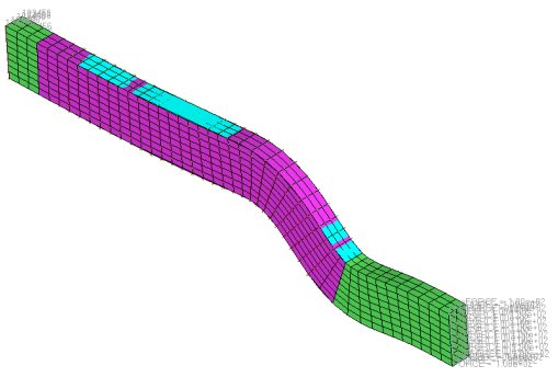
In this tutorial, you will perform a size and shape optimization on a structural rail to increase the buckling factor, thereby increasing the load it can carry before buckling. The rail has external forces applied at one end, and is constrained in all degrees of freedom at the other end. By performing buckling optimization, the buckling factor can be increased and thereby increase critical buckling force.
Structures are said to "buckle" when a certain combination of loads cause them to be unstable and deflection occurs. When a particular loading is reached, the structure continues to deflect without an increase in the magnitude of the load. The critical load at which buckling occurs is the product of the critical buckling factor and the applied reference load. The buckling factor is an eigenvalue and has no dimension. Generally speaking, the lowest buckling load is usually of the most interest to engineers, since a structure will fail prior to reaching any higher buckling loads.
When using OptiStruct to solve a linear buckling problem, apply a reference load to the structure and calculate the buckling factors based on linear static and normal mode analysis. Use OptiStruct also to perform size and/or shape optimizations on the structure to optimize for linear buckling. Neither yielding of a structure nor change of force can occur during the optimization process.
Buckling optimization needs be performed to minimize the maximum von Mises stress among several elements. This is done using the minimized maximum problem setup. Use MINMAX or MAXMIN statements to define the objective function of a minimize maximum or maximize minimum problem. Many times you will need to minimize or maximize several responses; minimizing the maximum von Mises stress among several elements, for example. In such situations, using user-defined equations to minimize the maximum von Mises stress will not achieve the expected result. Reducing the maximum stress in one element often results in increased stress on another element.
- Objective
- Minimize maximum von Mises stress.
- Constraints
- Increase first buckling factor above 30.
- Design Variables
- Element thickness and shape perturbation.
Launch HyperMesh and Set the OptiStruct User Profile
-
Launch HyperMesh.
The User Profile dialog opens.
-
Select OptiStruct and click
OK.
This loads the user profile. It includes the appropriate template, macro menu, and import reader, paring down the functionality of HyperMesh to what is relevant for generating models for OptiStruct.
Open the Model
- Click .
- Select the os_buckle_original.hm file you saved to your working directory.
-
Click Open.
The os_buckle_original.hm database is loaded into the current HyperMesh session, replacing any existing data.
Set Up the Optimization
Review the Design Variables and Animation of Shape Changes
- From the menu bar, click .
- In the Utility tab, click Opti.
- Under Optimization Info, click Design Variables.
-
In the Size and Shape Design Variables dialog, review the
pre-defined, v1 and v2 design variables and then click
Close.
The pre-defined design variables, v1 and v2, have an Initial Value of 0.0, Lower Bound of -2.0, and Upper Bound of 2.0.
Figure 2. 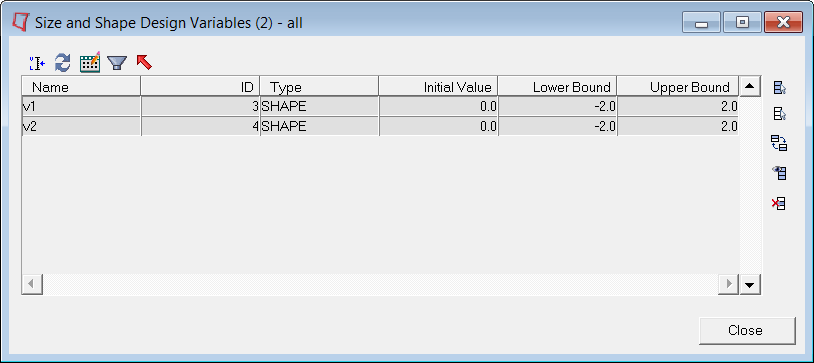
- From the Analysis page, click the optimization panel.
- Click the shape panel.
- Select the desvar subpanel.
- Click animate.
-
Animate the shape, SHAPE - v1 (1).
- Click simulation = and select SHAPE - v1 (1).
- Set data type = and select Perturbation Vector.
- Click linear.
- Review the animation of the first shape.
- Animate the shape, SHAPE - v2 (2).
- Click return three times to go back to the Optimization panel.
Define the Size Optimization Design Variable
- From the Analysis page, click the optimization panel.
- Click the gauge panel.
- Select the create subpanel.
- Set the type: to PSHELL-T and same desvar for all props.
- In the desvar= field, enter shells.
- Using the props selector, select dom and shell_elements.
- In the initial value = field, enter 6.0.
- Switch lower bound % = to lower bound =, and enter 3.0.
- Switch upper bound % to upper bound =, and enter 9.0.
- Click create.
- Click return twice to go back to the main menu.
Create Buckling Load Step Input
- In the Model Browser, right-click and select from the context menu.
- For Name, enter Buckling.
- For Config type, select Real Eigen value extraction from the drop-down.
- For Type, select EIGRL from the drop-down.
- For V1, enter 0.01.
-
For V2, enter 100.0.
OptiStruct will search for the three lowest eigenvalues below 100.
- For ND, enter 20.
Create a Buckling Optimization Load Step
- In the Model Browser, right-click and select from the context menu.
- For Name, enter Buckling.
- Click Color and select a color from the color palette.
- Set Analysis type to Linear Buckling.
-
Define STATSUB.
- For STATSUB, click .
- In the Select Loadcol dialog, select LINEAR and click OK.
-
Define METHOD(STRUCT).
- For METHOD(STRUCT), click .
- In the Select Load Step Inputs dialog, select buckling and click OK.
Create Optimization Responses
- From the Analysis page, click optimization.
- Click Responses.
-
Create the volume response, which defines the volume fraction of the design
space.
- In the responses= field, enter Vol.
- Below response type, select volume.
- Set regional selection to by entity and no regionid.
- Using the props selector, select dom.
- Click create.
-
Create a static stress response.
- In the response= field, enter Von.
- Set the response type to static stress.
- Using the props selector, select dom Stress.
- Set the response selector to von mises.
- Under von mises, select both surfaces.
- Click create.
-
Create the buckling response.
- Click return to go back to the Optimization panel.
Define Constraints
- From the optimization panel, click the dconstraints panel.
-
Create the constraint, BUCKLE.
- In the constraint= field, enter BUCKLE.
- Check the box next to lower bound, then enter 30.
- Click response= and select Buckle.
- Using the loadsteps selector, select Buckling.
- Click create.
-
Create the constraint, Vol.
- In the constraint= field, enter VOL.
- Uncheck the box next to lower bound.
- Check the box next to upper bound, then enter 800000.
- Click response= and select Vol.
- Click create.
- Click return to go back to the Optimization panel.
Define the Objective Function
-
Create an objective reference.
-
Define the objective.
- Click the objective panel.
- Select minmax.
- Using the dobjrefs= selector, select MAX_STRESS.
- Click create.
- Click return to go back to the Optimization panel.
Run the Optimization
- From the Analysis page, click OptiStruct.
- Click save as.
-
In the Save As dialog, specify location to write the
OptiStruct model file and enter
os_buckle_optimization for filename.
For OptiStruct input decks, .fem is the recommended extension.
-
Click Save.
The input file field displays the filename and location specified in the Save As dialog.
- Set the export options toggle to all.
- Set the run options toggle to optimization.
- Set the memory options toggle to memory default.
-
Click OptiStruct to run the optimization.
The following message appears in the window at the completion of the job:
OPTIMIZATION HAS CONVERGED.
FEASIBLE DESIGN (ALL CONSTRAINTS SATISFIED).
OptiStruct also reports error messages if any exist. The file os_buckle_optimization.out can be opened in a text editor to find details regarding any errors. This file is written to the same directory as the .fem file. - Click Close.
View the Results
View the Animations
-
From the OptiStruct panel, click HyperView.
HyperView launches within the HyperMesh Desktop and loads the result file(s).
-
In the top, right of the application, use the navigations buttons to navigate
to the Design History (page 2).
Figure 3. 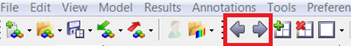
-
In the Results Browser, select Iteration
3.
Figure 4. 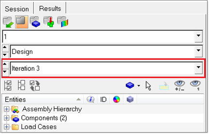
-
On the Results toolbar, click
 to open the Contour panel.
- Set the Result type to Shape Change (v) and Mag.
- Click Apply.
-
Animate the results.
-
On the Animation toolbar, click
 to start the animation.
Figure 5. 
Figure 6. 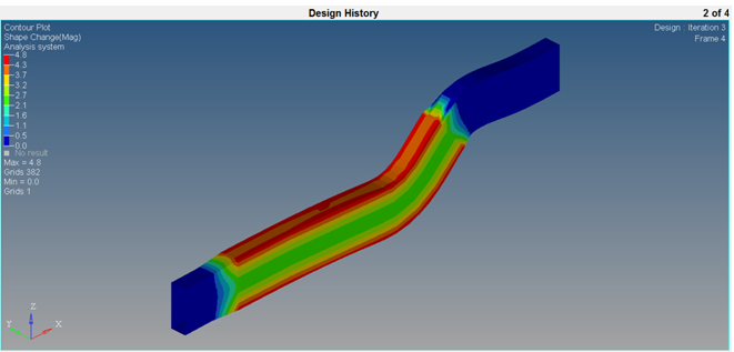
-
On the Animation toolbar, click
View the Stresses
-
In the top, right of the application, click
 to proceed to the next page (page 3 of 4),
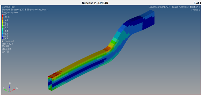
which contains the Linear analysis results.
to proceed to the next page (page 3 of 4),
which contains the Linear analysis results.
-
On the Results toolbar, click to open the
Contour panel.
- Set the Result type to Element Stresses (2D&3D)(t) and vonMises.
- In the Results Browser, select the final iteration (Iteration 3).
- Click Apply.
View the Buckling Modes
-
In the top, right of the application, click to proceed to the next page (page 4 of 4), which contains the buckling
results.
-
On the Results toolbar, click
 to open the Deformed panel.
-
Set the deformed shape parameters.
This will improve the animation visualization.
- Set Result type to Buckling mode(v).
- Set Scale to Model units.
- Set Type to Uniform.
- For Value, enter 10.
- Set Resolved in to Global System (proj: none).
-
Animate the model.
-
On the Animation toolbar, click to start the animation.
-
On the Animation toolbar, click