OS-T: 5020 3D Bracket Model using the Free-shape Method
In this tutorial you will perform a shape optimization on a solid bracket model using the Free Shape optimization method. The objective of this optimization is to reduce the stress by changing the geometry of the bracket model.
- Objective
- Minimize (Max von Mises Stress).
- Constraints
- No Constraints.
- Design Variables
- Grids move normal to the surface.
Launch HyperMesh and Set the OptiStruct User Profile
-
Launch HyperMesh.
The User Profile dialog opens.
-
Select OptiStruct and click
OK.
This loads the user profile. It includes the appropriate template, macro menu, and import reader, paring down the functionality of HyperMesh to what is relevant for generating models for OptiStruct.
Open the Model
- Click .
- Select the free_shape3D.hm file you saved to your working directory.
-
Click Open.
The free_shape3D.hm database is loaded into the current HyperMesh session, replacing any existing data.
Set Up the Optimization
Create Free-shape Design Variables
- From the Analysis page, click the optimization panel.
- Click the free shape panel.
- In the name= field, enter shape.
-
Using the nodes selector, select the nodes shown in Figure 2. Sselect only the face nodes that are also on
shells.
Figure 2. Free-shape Design Space 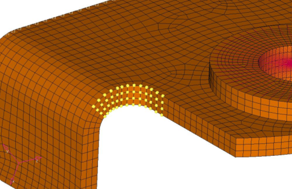
- Click create.
- Click return to go to the main menu.
Create Optimization Responses
- From the Analysis page, click optimization.
- Click Responses.
-
Create a static stress response.
- In the response= field, enter Stress.
- Set the response type to static stress.
- Using the props selector, select stress_faces.
- Set the response selector to von mises.
- Under von mises, select both surfaces.
- Click create.
- Click return to go back to the Optimization panel.
Define the Objective Function
-
Create an objective reference.
-
Define the objective.
- Click the objective panel.
- Select minmax.
- Using the dobjrefs= selector, select MAX_STR.
- Click create.
- Click return to go back to the Optimization panel.
Define the SHAPE Card
- From the Analysis page, click the control cards panel.
- In the Card Image dialog, click SHAPE.
- Set FORMAT to H3D.
- Set TYPE to ALL.
- Set OPTION to ALL.
- Click return twice to go back to the main menu.
Run the Optimization
- From the Analysis page, click OptiStruct.
- Click save as.
-
In the Save As dialog, specify location to write the
OptiStruct model file and enter
Free_Shape3D for filename.
For OptiStruct input decks, .fem is the recommended extension.
-
Click Save.
The input file field displays the filename and location specified in the Save As dialog.
- Set the export options toggle to all.
- Set the run options toggle to optimization.
- Set the memory options toggle to memory default.
-
Click OptiStruct to run the optimization.
The following message appears in the window at the completion of the job:
OPTIMIZATION HAS CONVERGED.
FEASIBLE DESIGN (ALL CONSTRAINTS SATISFIED).
OptiStruct also reports error messages if any exist. The file Free_Shape3D.out can be opened in a text editor to find details regarding any errors. This file is written to the same directory as the .fem file. - Click Close.
View the Results
View the Shape Results
-
From the OptiStruct panel, click HyperView.
HyperView launches within the HyperMesh Desktop and loads Free_Shape3D_des.h3d file in page 2 and the Free_Shape3D.h3d file in page 3.
-
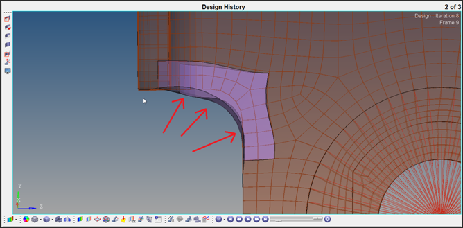
In the top, right of the application, use the navigations buttons to navigate
to the Design History (page 2).
Figure 3. 
-
In the Results Browser, select the last iteration
(Iteration 8).
Figure 4. 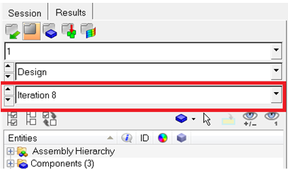
-
On the Results toolbar, click
 to open the Deformed panel.
- Set the Result type: to Shape change.
- Click Apply.
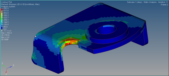
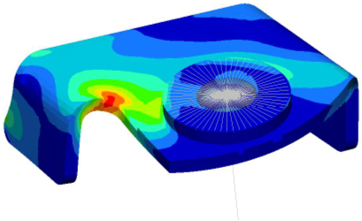
View a Contour Plot of the Stress
-
In the top, right of the application, use the navigations buttons to navigate
to the Subcase 1 - step (page 3).
Figure 6.
-
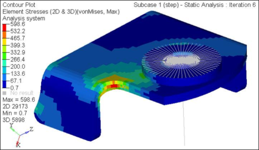
In the Results Browser, select the last iteration
(iteration 8).
Figure 7.
-
On the Results toolbar, click
 to open the Contour panel.
- Set the Result type to Element Stresses [2D & 3D].
- Set the stress type to von Mises.
- Click Apply.
Set Up a New Free-shape Optimization Simulation with Moving Constraints
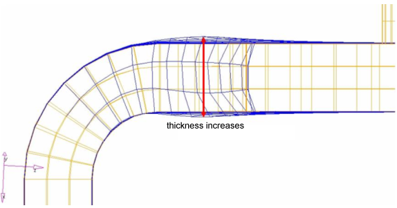
In practice, however, there will be some sort of constraints imposed upon the movement of grids due to manufacturability. For this tutorial model, thickness must be unchanged to avoid any interference with other parts.
In this step you will define constraints on DSHAPE grids such that the thickness of design space will remain unchanged.
The constraints on the curved part will be created using a local rectangular coordinate system (the other constraints on the flat part do not need a local coordinate system). Therefore, a local rectangular coordinate system (z-axis will point to normal to DSHAPE surface) needs to be created first.
-
In the top, right of the application, click
 /
/ to
move back to Page 1 and the HyperMesh client.
to
move back to Page 1 and the HyperMesh client.
- In HyperMesh, click return.
-
Define a local coordinate system.
- From the 1D page, click the systems panel.
- Select the create by axis direction subpanel.
- Click , then enter 20999 in the id= field.
- Click origin and enter 20999 in the id= field.
- Click x-axis and enter 15989 in the id= field.
- Click xy-plane and enter 19462 in the id= field.
- Click create.
- Click return.
Figure 11. Local Coordinate System 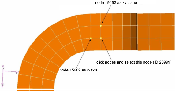
- From the Analysis page, click the optimization panel.
- Click the free shape panel.
- Select the gridcon subpanel.
-
Create constraints on the flat part without any coordinate system.
-
Using the nodes selector, select the nodes shown in Figure 12.
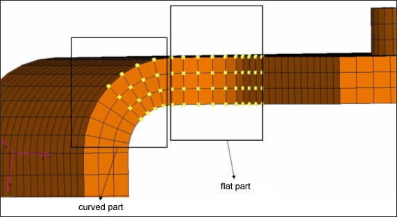
Figure 12. Constraints On Free Shape Design Space 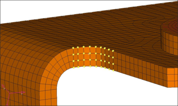
-
Using the N1, N2, and N3 selectors, select the three nodes on plane
geometry.
Figure 13. Three Nodes To Defined The Plane 
These nodes will move only on the specified plane. -
Using the nodes selector, select the nodes shown in Figure 12.
-
Create constraints on the curved part using a local coordinate system.
-
Using the nodes selector, select the nodes shown in Figure 14.
Only select the nodes that are on the curved part.
Figure 14. Constraints On Free-shape Design Space On Curved Part 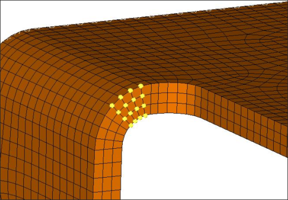
-
Using the nodes selector, select the nodes shown in Figure 14.
- Click return twice to get back to the main menu.
Run the Optimization
- From the Analysis page, click OptiStruct.
- Click save as.
-
In the Save As dialog, specify location to write the
OptiStruct model file and enter
Free_Shape3D_const for filename.
For OptiStruct input decks, .fem is the recommended extension.
-
Click Save.
The input file field displays the filename and location specified in the Save As dialog.
- Set the export options toggle to all.
- Set the run options toggle to optimization.
- Set the memory options toggle to memory default.
-
Click OptiStruct to run the optimization.
The following message appears in the window at the completion of the job:
OPTIMIZATION HAS CONVERGED.
FEASIBLE DESIGN (ALL CONSTRAINTS SATISFIED).
OptiStruct also reports error messages if any exist. The file Free_Shape3D_const.out can be opened in a text editor to find details regarding any errors. This file is written to the same directory as the .fem file. - Click Close.
View the Results