Create Doubler Design Enablers
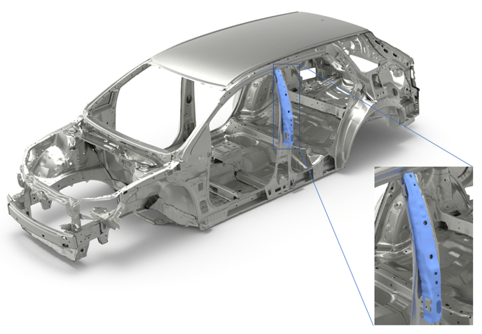
Doublers are design enablers that provide localized performance benefits for multiple design attributes such as NVH, Safety, and so on.
When their position and thickness are precisely designed, doublers can reduce mass and increase performance as they eliminate up-gauging of entire part(s). Typically, doublers are typically welded on one side and bonded with structural adhesive on the other side and can be incorporated even during the late stages of the product design cycle.
-
From the Concept ribbon, click the Doubler tool.
Figure 2. 
-
With the Element selector active on the guide bar,
select the elements where the doubler needs to be roughly located.
Figure 3. 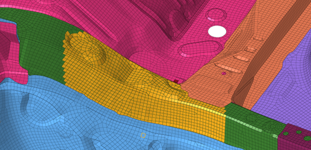
-
Click Base on the guide bar then
select the base node.
Note: The base node must be on the longest face of the selected elements. Figure 4 shows correct “Base” node selection. Figure 5 shows incorrect “Base” node selection that will not create a bulkhead.
Figure 4. Correct "Base" Node Selection (From the Longest Face) 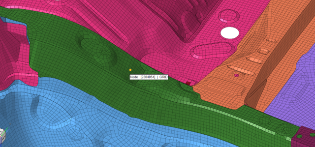
Figure 5. Incorrect "Base" Node Selection 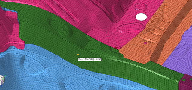
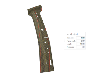
- Use the microdialog to edit the thickness of the doubler, the flange width, the length, and the mesh size.
- Optional:
Use the other icons in the microdialog to further
define the doubler.
- Click
 to modify the direction and
orientation.
to modify the direction and
orientation. - Click
 to select a
material.
to select a
material. - Click
 to select predefined connection
control.
to select predefined connection
control. - Click
 to select edges to differentiate flanges from
doubler face (see Doubler Edge Selection).
to select edges to differentiate flanges from
doubler face (see Doubler Edge Selection).Figure 6. Edge Selection 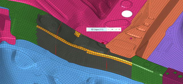
- Click
-
Click
 on the guide bar.
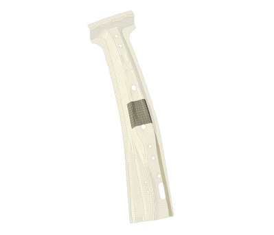
The doubler is created within a new component. The appropriate property card image (for example, PSHELL for the OptiStruct solver profile) is also created.
on the guide bar.
The doubler is created within a new component. The appropriate property card image (for example, PSHELL for the OptiStruct solver profile) is also created.Figure 7. Doubler Preview 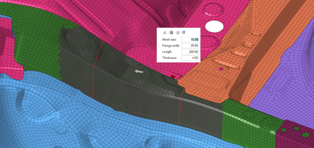
Figure 8. Doubler Parameters With Material and Connection Control Selection 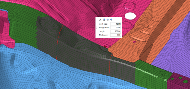
Figure 9. Doubler With Connectors 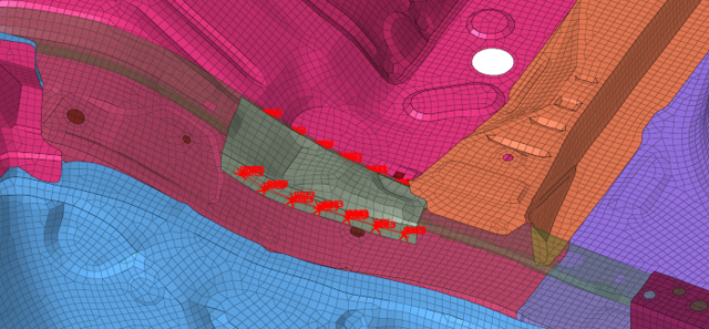
Doubler Edge Selection
If the section selected to create the doubler does not have sharp edges, the doubler tool may fail to generate an appropriate preview. In such cases, the following steps can assist to create a doubler.
-
Click to rectify the orientation of the doubler.
-
Set the correct orientation options, which can be seen in Figure 11.
Figure 11. Use of Vector to Rectify the Orientation of the Doubler 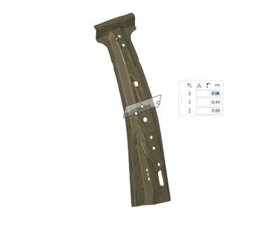
-
Press Esc to return to the
doubler microdialog.
Figure 12. Correct Doubler Orientation 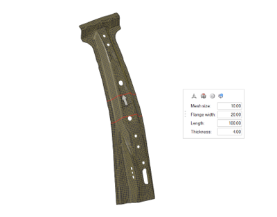
-
Click to enter the edge selection mode.
- Deselect existing edges using Shift+ left mouse selection window.
- Set the edge selection angle to 10◦ using Shift + mouse scroll.
-
Select two edges to differentiate between the doubler face and flanges (Figure 13).
Figure 13. Selection of Edges 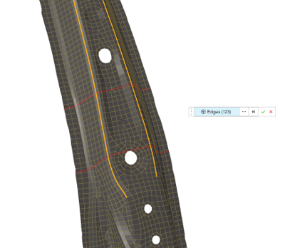
-
Press Esc to return to the
doubler microdialog.
Figure 14. Doubler Preview with Correct Orientation and Edges 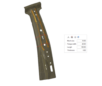
-
Click on the guide bar.
Figure 15. Doubler After Edge Selection