Create Bulkhead Design Enablers
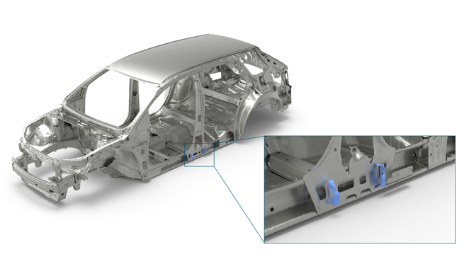
Bulkheads are design enablers that provide localized performance benefits for multiple design attributes such as NVH, Safety, and so on.
When their position and thickness are precisely designed, bulkheads can reduce mass and increase performance as they eliminate up-gauging of entire part(s). Typically, bulkheads are welded on one side and bonded with a structural adhesive on the other side and can be incorporated even during the late stages of the product design cycle.
-
From the Concept ribbon, click the Bulkhead tool.
Figure 2. 
-
With the Element selector active on the guide bar,
select the elements where the bulkhead needs to be roughly located.
Figure 3. 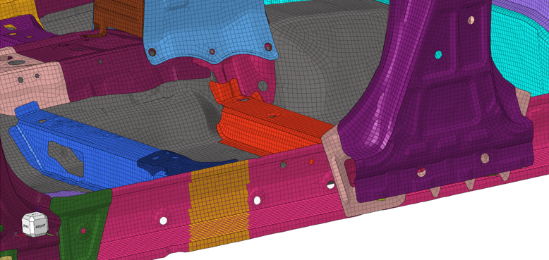
-
Click Base on the guide bar then
select the base node.
Note: The base node must be on the longest face of the selected elements. Figure 4 shows correct “Base” node selection. Figure 5 shows incorrect “Base” node selection that will not create a bulkhead.
Figure 4. Correct "Base" Node Selection (From the Longest Face) 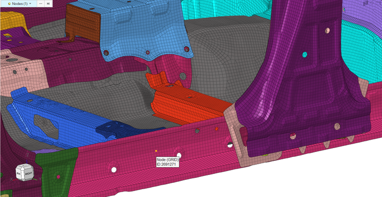
Figure 5. Incorrect "Base" Node Selection 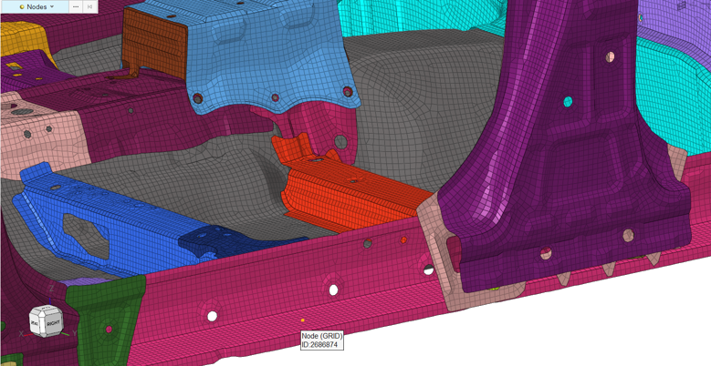
-
Use the microdialog to edit the thickness of the
bulkhead, the flange width, and the mesh size.
Additionally,
 can be used to reverse flange direction and
  can be used to modify the direction and orientation of the bulkhead.
 - Optional:
Click
 to select a material for the
bulkhead.
to select a material for the
bulkhead.
-
Click
 on the guide bar.
The bulkhead is created within a new component. The appropriate property card image (for example, PSHELL for the OptiStruct solver profile) is also created.
on the guide bar.
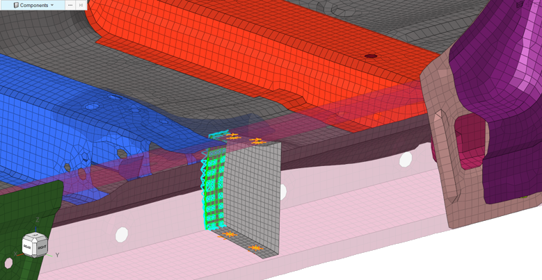
The bulkhead is created within a new component. The appropriate property card image (for example, PSHELL for the OptiStruct solver profile) is also created.Figure 6. Bulkhead Creation Completed 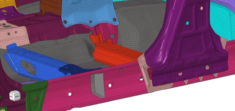
To complete the process, use connectors to attach the bulkhead to the surrounding part(s).Figure 7. Bulkhead With Connectors