Use the Define Interface tool to create, import, and edit geometric lines along the
interfaces to evaluate.
These lines are required in the E-Line definition stage. Using the
Define Interface tool, you can:
Create 3D lines
Import geometry file
Edit 3D lines
Create 3D Lines
Use the Define Interface tool to manually or automatically create 3D lines on the
component edges.
3D lines can be created automatically or manually. Manual
creation of 3D lines along the required node path require manual inputs and provides
more control over line creation.
From the SnRD ribbon, Setup
group, select the Define Interfaces tool from the Define
Interface tool group.
Figure 1.
Fast create geometric lines.
Optional: From the guide bar, click to define feature options and control
Geometrical Lines creation.
Figure 2.
The available options are:
Feature Angle: The maximum angle allowed between the normals of
two connected shell elements. When an angle exceeds this value,
a geometrical line is created.
Break Angle: The angle to determine points at which to split the
line into segments.
Min: Minimum length of lines which will be created.
Max: Maximum length of lines which will be created.
In the modeling window, select
components.
From the guide bar, complete one of the
following options:
Click to create lines and remain in
the tool.
Click to create lines and exit the
tool.
Click to exit the tool without
creating lines.
Geometric lines are created on the selected component
edges.
Manually create geometric lines.
From the guide bar, click to create lines manually by node
path.
Optional: From the guide bar, click to define controlled line
creation.
This creates controlled lines between locations with the
possibility of reducing the number of joints and locations that fall
outside the path line.
In the modeling window, create click twice to
define the endpoints of the line.
Optional: In the microdialog, click to select a line
type.
From the guide bar, complete one of the
following options:lick to finalize the geometric
line and continue creating lines.
Click to finalize the geometric
line and continue creating lines.
Click to finalize the geometric
line and exit the tool.
Click to exit the tool without
finalizing the geometric line.
Import Geometry File
Import a geometry lines definition file.
You can import an external file containing the geometric
lines definition. File formats are standard file formats supported by HyperWorks X.
From the SnRD ribbon, Setup
group, select the Import Geometry tool from the Define
Interface tool group.
Figure 3.
The Open Geometry File dialog opens.
Browse and select the required file and click
Open.
Once the file is opened, the lines in
the external files are imported to the session and displayed in the graphics
area.
Edit 3D Lines
Edit geometric lines. In the model, you can delete, combine, and split
lines.
Delete Lines
Delete required lines from the model.
From the SnRD ribbon, Setup
group, click the Review/Edit Interfaces tool from the
Define Interface tool group.
Figure 4.
From the guide bar, verify Delete
is selected.
Click to define the line length
criteria.
Figure 5.
Click Find.
Tip: If you created lines on all component
edges, you can use the find functionality to delete all short lines. This
can make line selection at the E-Line creation stage
easier.
All lines within the line length range are found.
Optional: In the modeling window, manually select the required
lines.
The number of lines selected to delete are displayed next to the Line
button.
Complete one of the following options:
Click to delete the selected
lines.
Click to delete the selected lines
and exit the tool.
Click to exit the tool without
deleting the selected lines.
This deletes the selected lines.
Combine Lines
Combine two or more lines to form a continuous line.
Tip: The more accurate and well defined your
interfaces (geometrical lines) are, the less time you have to spend editing and
updating E-Lines at a later stage. Make sure you have one
Geometrical line per interface.
From the SnRD ribbon, Setup
group, click the Review/Edit Interfaces tool from the
Define Interface tool group.
Figure 6.
From the guide bar, select
Combine.
In the modeling window, left-click to select lines to
combine.
Complete one of the following options:
Click to combine lines and remain
in the tool.
Click to combine lines and exit the
tool.
Click to exit the tool without
combining lines.
Split Lines
Split geometric lines.
From the SnRD ribbon, Setup
group, click the Review/Edit Interfaces tool from the
Define Interface tool group.
Figure 7.
From the guide bar, select
Split.
The Split tool is activated from the Topology ribbon.
From the secondary ribbon, select the Lines tool.
Figure 8.
From the guide bar, select Lines
from the Target selector.
In the modeling window, select geometry.
Optional: On the guide bar, click to define split
options.
 Figure 1.
  to define feature options and control
Geometrical Lines creation.
to define feature options and control
Geometrical Lines creation.
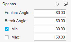 Figure 2.
  to create lines and remain in
the tool.
to create lines and remain in
the tool. to create lines and exit the
tool.
to create lines and exit the
tool. to exit the tool without
creating lines.
to exit the tool without
creating lines. to create lines manually by node
path.
to create lines manually by node
path.
 to select a line
type.
to select a line
type.
 Figure 3. The Open Geometry File dialog opens.
 Figure 4.
 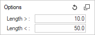 Figure 5.
  to delete the selected
lines.
to delete the selected
lines. Figure 8.
  to define split
options.
to define split
options.