
Extract Points and Nodes
Use the Extract Points/Nodes tool to interpolate and divide an edge or line, and find the center of an arc, fillet, or multiple curve segments.
-
From the Geometry ribbon, click the arrow next to the
Create tool set, then select
Extract Points.
Figure 1. 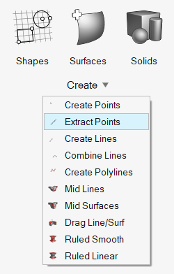
- Optional:
From the guide bar, click
 and select Enable topology
color mode.
The next time the tool is opened, topology color mode will be enabled automatically.
and select Enable topology
color mode.
The next time the tool is opened, topology color mode will be enabled automatically. -
From the drop-down menu below the tool, select what to extract.
- Extract Points
- Extract Nodes
- Extract Points at Intersection
- Extract Nodes at Intersection
-
Extract points/nodes in the following ways:
Option Description Interpolate Points/Nodes - Click on a line.
- In the microdialog, enter the number of
points/nodes to extract and press Enter.
Figure 2. 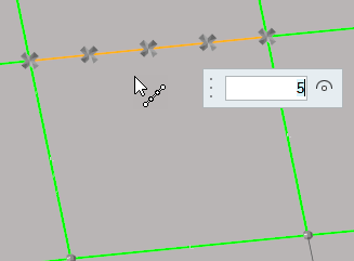
New points are organized in the same component as their source line.
Tip:- Re-interpolate the number of points/nodes on the selected line by entering a new value in the microdialog and pressing Enter.
- When interpolating from multiple lines, the same number of points/nodes will be created on each line and distributed evenly along their respective source line’s length.
- When interpolating from a closed loop, the start and end points/nodes are the same, but separate points/nodes will be created at each location. To divide a circle into four equal lines, interpolate five points/nodes.
Find Curve Center - Click on an arc.
- In the microdialog, click
 .Note: When calculating the curve center of multiple lines, a single point/node is created at the best matching curve center of the combined lines.
Figure 3. 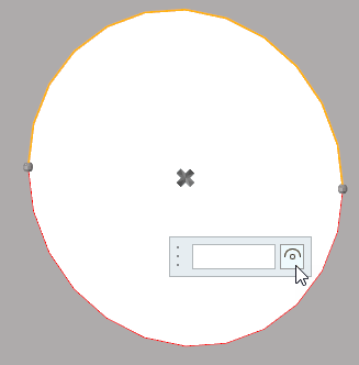
Extract Parametric Create nodes at parametric locations on lines and surfaces. - From the guide bar, click to define the U and V lower and
upper bounds.
- For lines
-
- 0.0 <= u lower bound <= u upper bound <= 1.0.
- If the lower and upper bounds are the same, only one node is created.
- If the number of u nodes is specified as 1, only the lower bound is used.
- The line parameterization type can be specified as either arc length or internal. Internal parameterizations depend on how the line was originally created, while arc length simply distributes the nodes uniformly.
-
Figure 4. Nodes Created on a Line. This example uses u lower bound 0, u upper bound 0.75, u nodes = 5, and arc length parameterization. 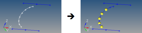
- For surfaces
-
- 0.0 <= u lower bound <= u upper bound <= 1.0.
- 0.0 <= v lower bound <= v upper bound <= 1.0.
- The number of u and v nodes must be >= 1.
- The total number of nodes created equals (number of u nodes * number of v nodes).
- The surface parametric area is scaled to the visible surface area. Nodes will be created inside the visible surface area.
-
Figure 5. Nodes Created on a Surface. In this example, u ranges from 0 to 0.75 with 5 nodes, while v ranges from 0 to 0.66 with 3 nodes. 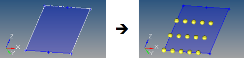
Extract Points/Nodes at Intersection - From the guide bar, select an entity.
- From the modeling window, select geometry.
- From the guide bar, select Direction or Lines.
- From the modeling window, select geometry.
Figure 6. Node Created at Each Intersection Location 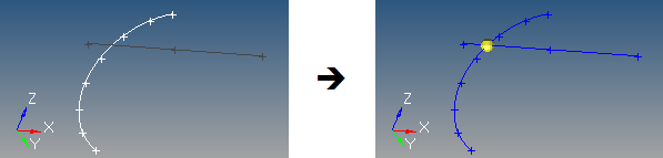
Figure 7. New Point Created from Lines 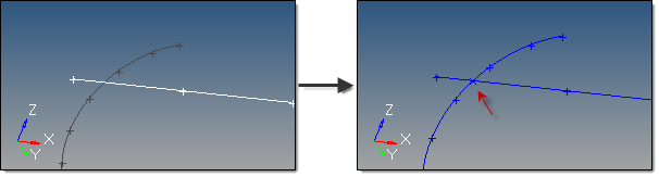
For surface, solid, and plane intersections, if the input line or vector lies on the surface/solid/plane the result is undefined and unpredictable.
For vectors, the magnitude and direction of the vector do not have any effect on the result. The vector extends through the entire model space.
-
On the guide bar, complete one of the following:
- Click
 to apply and stay in the tool.
 - Click
 to apply and close the tool.
 - Click
 to exit the tool without applying.
- Click