In AcuSolve enclosure or surface to surface radiation
models, effect of media between surfaces is ignored. This assumption is acceptable
when you are dealing with lower temperature fluids. Nonetheless, while you have
semi-transparent media like glass or high temperature gases like in flames, effect
of media should be considered in heat transfer analysis. Two models are available in
AcuSolve: A simple one equation P1 model
and more detailed but expensive discrete ordinates (DO) model.
Radiative Transfer Equation (RTE)
Radiative energy balance in a participating media is governed by the following
integro-differential equation, known as the radiative transfer equation
(RTE):
where is the radiation intensity, is the spatial vector, is the unit directional vector, is the scattering directional vector, is the absorption coefficient, and is the scattering coefficient, is an emission,
n the refractive index, and is the Stefan-Boltzman constant (5.67 ×
10-8 W m-2 K-4). T is the temperature (K).
P1 radiation model
Discrete Ordinates (DO) model
P1 Radiation Model
The P1 model is the lowest order PN (spherical harmonics) type
radiation model. The method reduces the five independent variables of the Radiative
Transfer Equation (RTE) into a PDE that is relatively simple in comparison. The
model is the most computationally efficient of the radiation models in AcuSolve, but it can lose accuracy, under certain conditions,
for optically thin media. It performs best in scenarios where the radiative
intensity is near isotropic.
Governing Equation
P1 approximation and assumptions
The P1 model is derived from the general PN formulation (a
spherical harmonic series expansion of the radiative intensity for the angular
variable) by assuming that the series is limited to four terms and integrating over
all solid angles. From the first harmonic in the series approximation, the
divergence of the radiative flux () can be derived by integrating the RTE over all
solid angles as
where is the incident radiation , is the absorption coefficient, the refractive index, and is the Stefan-Boltzman constant (5.67 ×
10-8 W m-2 K-4),
is the radiative flux.
Additionally, a second vector equation can be derived from the other three harmonic
terms for the radiative flux
where is the diffusion coefficient.
By taking the divergence of (2), and substituting into this the right hand side of
equation (1), leads to elimination of the heat flux. The final diffusion reaction
equation describing the transport of incident radiation is given by
where is a diffusion coefficient given by
where is the absorption coefficient, is the scattering coefficient, and
is the linear-anisotropic phase
function.
Anisotropic scattering
The implementation in AcuSolve includes the ability to
model linear anisotropic scattering
where is the unit directional vector in the scattering
direction, is the unit directional vector in the incident
radiation direction. This term is included in the scattering term of the RTE along
with the four term spherical harmonic expansion of the radiative intensity field
(the first term being isotropic and the other three anisotropic). The final form of
the P1 approximation in equation (3) includes this term. The values of
the phase function A1 have the following meaning:
A1 = 1: More radiation is scattered in the forward direction
A1= -1: More radiation is scattered in the backward
direction
A1= 0: Isotropic scattering
Coupling to energy equation
The source term in equation (1) can be substituted into the energy equation as a
negative source since a local increase in radiative heat flux is due to a local
decrease in thermal energy.
In AcuSolve the default stagger sequence when the
P1 radiative heat transfer solver is enabled is:
Solve the energy equation with source term (
κ(4n2σT4-G) ), where G is zero for the
time step
Pass temperature to radiation solver and solve equation (3)
Repeat until converged
Boundary Conditions
Marshak's boundary condition
Based on the assumption that the walls are diffused gray surfaces, that is,
independent of wavelength, the appropriate wall boundary condition
is
where is the surface emissivity,
is the wall temperature, and the wall incident radiation. The boundary radiative
heat flux can be calculated from the incident radiation and the temperature at the
wall:
Discrete Ordinates (DO) Model
Governing equation
The governing equation is the radiative transfer equation limited to a finite number
of directions (or ordinates)
Scattering term (source term)
The integral over all the directions in equation (1) is replaced by a numerical
quadrature for different ordinate
directions ()
The phase function, , is given
by
Boundary conditions (RTE)
Diffused surface
If a surface emits and reflects diffusely, the exiting intensity is directionally
independent and is given by
Specular and diffuse surface
The diffused fraction defines the proportion of reflected radiation intensity at a
surface which is diffused, that is, the reflection may also have a specular
component. If the radiation intensity reflection coefficient at the surface is
defined by
then the diffused reflection coefficient, , is defined in terms of the diffused fraction and the emissivity of the surface by
and the specular reflection coefficient
If =1, then the reflection at the surface is completely
diffused. If =0 then the reflection is specular. The outgoing
intensity, I, at the surface in terms of the above two reflection coefficients is
given by
where the first terms represent emission from the surface, the second term the
diffused component incoming radiation heat flux and the third the specular
component. The diffused component represents a sum over all radiation intensities
along ordinates that are incident to the surface (that is, a hemisphere of incoming
radiation to the surface); is the normal into the domain and the jth ordinate direction. The ordinate direction (), the total number of ordinate directions () and the weights () are automatically defined by the order of the
radiation_quadrature (S2, S4, S6, S8 & S10). The specular ordinate direction () is the direction that the radiation intensity must
strike the surface to reflect in a specular fashion along the outgoing ordinate
direction, , and is given by
which means the angle that incident radiation intensity strikes the surface equals
the angle of reflection.
Boundary conditions (Energy equation)
Interface and outflow/inflow boundary conditions
At an opaque interface between participating and non-participating media or
outflows/inflows a radiative heat flux must be added to the boundaries in the energy
equation. This flux is given by
For an opening, that is, outflow or inflow, the black body intensity used in the
calculation of the outgoing intensity at the surface is based on the opening
temperature of the surrounding:
while for an interface it is based on the current temperature solution.
Output metrics
Two directionally integrated output metrics can be derived from the radiative
intensities: incident radiation and radiative heat flux.
Incident radiation
Incident radiation is the total intensity impinging on a point from all directions
and is given by
where is the intensity in direction i, the number of ordinates, the weights.
Interface Between two Semitransparent Media
At the interface between two semitransparent media (referred to as medium 1 and
medium 2 below), radiative intensity is both transmitted and reflected. The
proportion of transmitted and reflected intensity at the interface depends on: the
refractive indices (n1, n2) of the two media; the incident
angle that radiative intensity strikes the surface; and the diffuse fraction of the
surface.
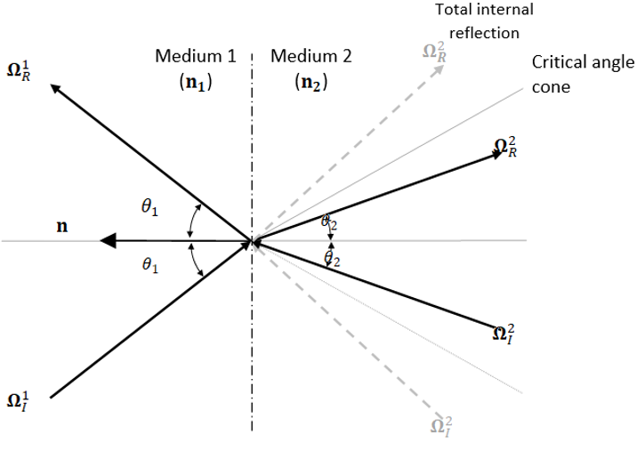
Reflection and transmission for specular interfaces
Reflection at an interface is governed by the angle of incidence of a radiative
intensity and the refractive indices of the two media. The image below shows the
different refracted and reflected rays between two media.Figure 1. Reflected and refracted directions at the interface between two
participating media of different refractive indices (n1 <
n2). For the medium of higher refractive index if the
incoming direction is greater than the critical angle total internal
reflection occurs (no transmission occurs across the interface). This is
represented by the gray dashed lines in the image.
The cosine of the incident angle for the incoming ordinate is given
by
where is the outward facing normal direction at the
interface (towards the second medium) and is the unit direction of incoming radiative
intensity to the surface, given by
where is the unit reflected ordinate
direction vector and also represents the current ordinate direction being solved.
The equivalent calculation can also be performed for medium two.
Radiative intensity that is transmitted into a second medium undergoes refraction
governed by Snell's law,
where n1 and n2 are the refractive indices of mediums.
θ1 and θ2 are the angles of incidence and refraction of
radiative intensity relative to the interface normal, respectively. This can also be
represented in vector form by
The incoming direction vector in medium two for a ray refracted from medium two to
one is given by
The above expression is valid providing the expression under the radicand is greater
than zero; otherwise total internal reflection occurs.
The actual reflected and refracted directions differ slightly from the calculated
direction since these directions will unlikely coincide with a discrete ordinate
direction. Since the number of directions is governed by the order of radiation
quadrature, higher quadrature orders are more accurate for interface problems.Figure 2. Octant of angular quadrature with transmission direction. The calculated
transmission direction (ΩT) is shifted to match the nearest
quadrature point.
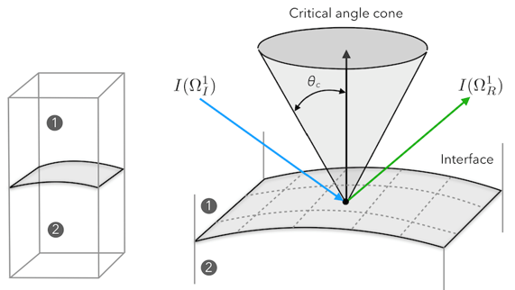
Depending on the refractive indices of the two media and the angle of incidence,
θ1, the proportion of radiation intensity that is reflected or
transmitted will vary. If , then the radiative intensity in medium one will be
partially reflected and partially transmitted into a cone defined by the critical
angle, θc, which is given by:
and defines a cone in 3D (see the images below). The critical angle is defined by a
ray that grazes the surface on the side of medium 2 and is transmitted exactly at
the critical angle in medium 1. As an example, if and , the direction of incoming radiation is greater than
the critical angle and total internal reflection will occur. This means the incoming
ray is reflected at the same angle of incidence and no transmission occurs.Figure 3. Total internal reflection of intensity rays at an interface (). The critical angle cone defines the angle
outside which total internal reflection occurs, that is, .
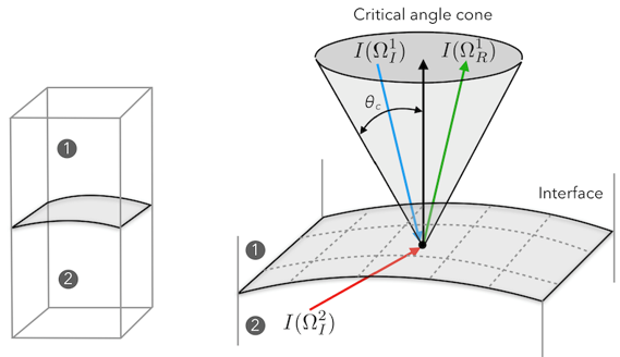
However, if , the outgoing intensity will include transmission
from medium 2 to medium 1, as shown in the image below.Figure 4. Reflection and transmission of intensity rays at an interface () for
At the interface, the intensity is partially reflected and transmitted into the other
medium if or the outgoing direction is in medium 2. The
reflected proportion from , or reflectance, is given by
and the transmitted proportion from the , or transmittance, is given by
In the second medium, for the current scenario where , if the radiative intensity is, as for medium one,
partially reflected and partially transmitted. The reflection coefficient is as
described above since . If , then total internal reflection occurs and and ,
meaning no transmission of radiative intensity into the second medium or from the
first medium. This is shown in the image above with the gray dashed lines.
From the above, the outgoing radiative intensity on the side one of the interface for
the current ordinate direction, is given by
where for medium one, the first term on the right-hand side represents the reflected
intensity in medium one and the second term represents the transmitted intensity
from medium two to one. For medium two, if the current ordinate direction is then the intensity outgoing radiative intensity is
given by
For , the subscripts of the above
analysis must be exchanged, and total internal reflection will now occur in medium
one.
Reflection and transmission for diffuse interfaces
If the interface is diffused, for example, diffused_fraction = 1.0, the reflectivity
of the interface is given by the hemispherically averaged
reflectance:
where is the ratio of refractive
indices.
Note: always represents
the medium with higher refractive index and
the medium of lower refractive
index.
The transmission from medium one to two is given by
For the reverse direction the reflectance and transmittance are given
by:
and
respectively.
The incoming radiative intensity to the interface is given by the hemispherically
averaged intensity for medium one and two:
where is the outward facing normal. From these fluxes, the
outgoing radiative intensity at the wall for the current ordinate direction, , is given by
Reflection and Transmission for partially specular and partially diffuse
interfaces
For partially specular and partially diffuse interfaces 0.0 < diffused fraction
< 1.0.
Interfaces between semi-transparent media are typically not 100 percent diffused or
specular and the diffuse fraction lies somewhere between zero and one. In this range
the outgoing radiative intensity is treated as a linear combination of the specular
and diffuse components, for example:
where is the diffuse fraction, is the outgoing specular component of radiative
intensity, and is the outgoing diffuse component of radiative
intensity. For example, in medium one in the image above the components would
be:
and
Specular and diffuse interfaces
For the interface equations to be applied weakly, Iw must be applied in
both mediums. If the current ordinate direction, , is outgoing from the interface in medium 1 then
Iw is equal to the proportion of radiative intensity reflected and
transmitted. From the analysis in the previous section, this would
be:
In medium 2 since the current ordinate direction, , is incoming to the surface no boundary flux is
added to the equation, that is, .
Reflection and Transmission for diffuse interfaces of Type External
Exchange of radiative intensity occurs for external surfaces when the medium inside
the computational domain is semitransparent. That is the medium surrounding, which
is not modeled using a computational mesh, participates in radiative transfer. For
this case a mathematical model of external radiation is used. The model assumes that
the surrounding medium has uniform radiative intensity in all directions, that is,
the radiative flux is isotropic. The isotropic radiative intensity is given by the
following blackbody source:
where is the external emissivity and is set to one, is the Stefan-Boltzmann constant, is the temperature of the surrounding medium. At the
external interface is transferred into
the medium. This condition can only be applied to boundaries as the interface is
only modeled mathematically.