Since version 2026, Flux 3D and Flux PEEC are no longer available.
Please use SimLab to create a new 3D project or to import an existing Flux 3D project.
Please use SimLab to create a new PEEC project (not possible to import an existing Flux PEEC project).
/!\ Documentation updates are in progress – some mentions of 3D may still appear.
Meshed coil regions
Introduction
Meshed coils in Flux are a type of face (in 2D) or volume (in 3D) region used to represent windings and other current-carrying conductors. As already mentioned in the topic Coils and windings in Flux, these regions provide an interface to an external electric circuit and are fully integrated into the finite element domain. Consequently, Flux can rely on the mesh available in these regions to evaluate relevant electromagnetic quantities (e.g., the magnetic induction, the current density, and the Joule loss density, among others) in the bulk of the conductor.
Since electric currents are sources of magnetic induction, an accurate evaluation of the current density distribution in a coil is of paramount importance in the design of electromagnetic devices. Moreover, the precise computation of this quantity plays a crucial role in the prediction of Joule losses. On the other hand, determining this distribution can be challenging because of well-known current concentration phenomena taking place in conducting media such as the skin and proximity effects.
- an overview of physical phenomena leading to an uneven current density distribution in coils and windings;
- a brief discussion on homogenization techniques and their importance in the modeling of windings and conductors;
- a comparative analysis of the two types of meshed coil regions available in Flux, namely the Coil Conductor region and the Solid Conductor region.
The Skin and Proximity Effects
When a coil is fed, the current density flowing in the conductor results in a non-uniform distribution in the general case. Several parameters influence the current density distribution in conductors, including:
- the conductivity of the conductor;
- its magnetic permeability ;
- the time rate of change of the current.
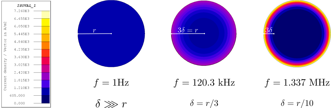
Physicists and Electrical Engineers use the term skin effect to explain current concentration phenomena linked to the parameters above. This term comes from the fact that, in the significant case of conductors subjected to a sinusoidal excitation at a frequency , a length given by
describes the depth below the conductor surface, concentrating a fixed portion of the current. This depth is called the skin depth, and one may show that about 95% (or 1-e-3) of the total current flows within a depth of three times in a conductor.
The skin effect may be interpreted in terms of an induced current density component flowing in the coil. This induced component modifies the overall current density distribution and opposes to magnetic flux variations dictated by the imposed current, as predicted by Faraday’s law of induction. The example in Figure 1 depicts the skin effect at increasing frequencies in a 1 mm2 round copper conductor traversed by a sinusoidal current with an amplitude of 1 mA.
Homogenization Techniques in Flux
Evaluating losses in thin multi-stranded conductors or coils with several turns with the finite element method can be a demanding task, since the method requires meshing devices with detailed geometries. A well-known rule of thumb recommends that the zone corresponding to the first two or three skin depths below the conductor surface should be finely discretized. However, satisfying this criterion frequently leads to complex meshes and high memory requirements, especially in 3D and at higher frequencies.
Flux deals with this trade-off between mesh complexity, use of computer resources, and accuracy by providing the user with two types of Meshed Coil regions: the solid conductor region and the coil conductor region.
Solid conductor regions are employed in Flux to represent an individual current-carrying conductor or a coil in its full geometrical complexity. They can take into account the skin and proximity effects rigorously and are useful when a detailed mapping of the current density distribution in the conductor is desired. On the other hand, they require elaborate geometrical and circuit descriptions and lead to complex meshes, a substantial memory usage, and relatively longer computation times.
Coil conductor regions, on the other hand, are well suited to model tightly packed windings, in which the positioning of the wire turns is given by the juxtaposition of a fixed motif or unit cell. In these regions, Flux performs a pre-computation on a unit cell to estimate the impact of the skin and proximity effects in the current density distribution. The results yielded by this pre-computation are then translated into equivalent material properties that are assigned to the coil conductor region. To have more information about these elementary cells, see this discussion.
Foil coil windings (wound metallic conducting sheet) can also be described by these regions, where Flux then applies the homogenization to compute with a dedicated FE formulation the impact of the skin and proximity effects on the current density distribution. It means that for foil or wire coils the homogenization strategies are not the same and so the quantities available in post-processing could be different. For more information about this model, see this discussion.
The technique described above homogenizes the winding representation (i.e., simplifies its geometrical description) and circumvent the previously mentioned difficulties related to solid conductor regions. However, it should be remarked that the equivalence between the non-homogenized and homogenized representations is not absolute. While the homogenization preserves the Joule losses and the stored magnetic energy, the evaluated current density distribution changes. In other words, the current density computed in a homogenized coil conductor region is not identical to the current density distribution predicted by a coil model based upon solid conductor regions.
The example in the next section compares the modeling of a simple winding with both solid conductor regions and a coil conductor region to further clarify these aspects.
Comparing Solid Conductor Regions and Coil Conductor Regions in Flux
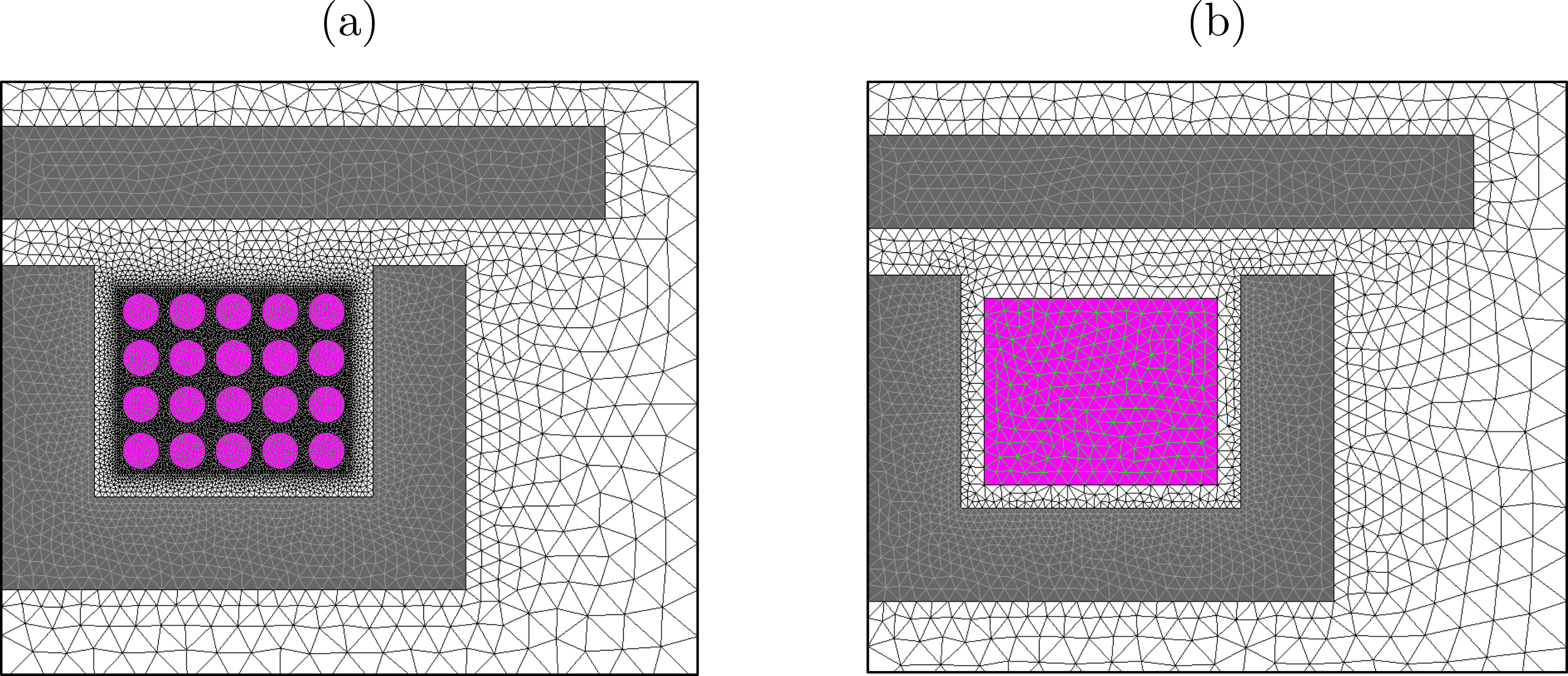
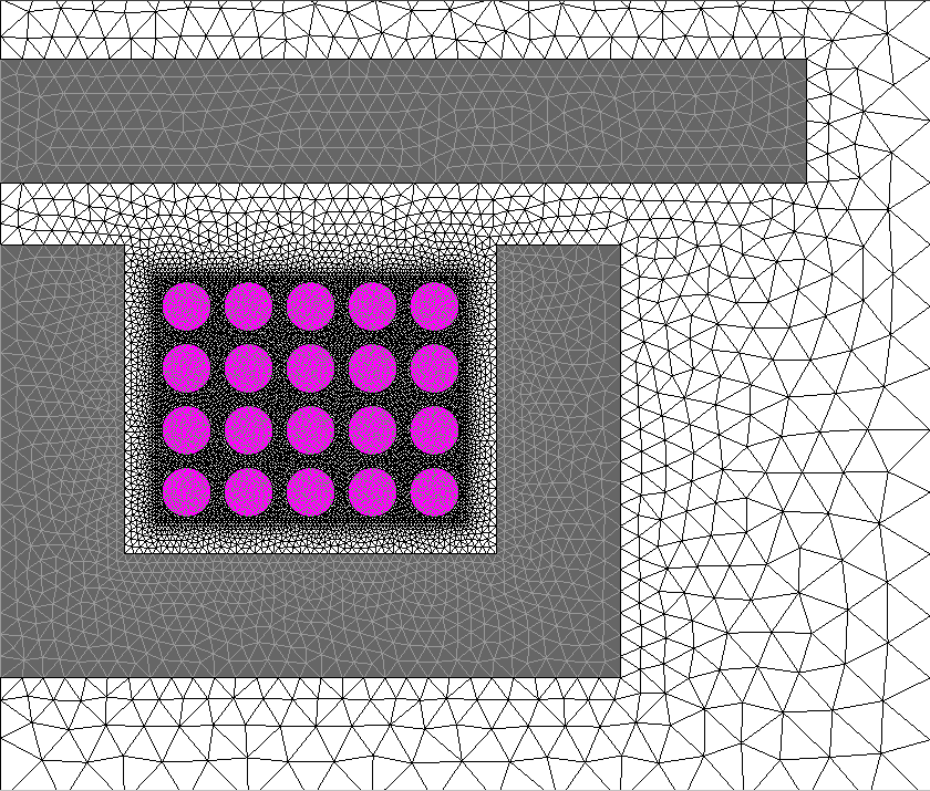
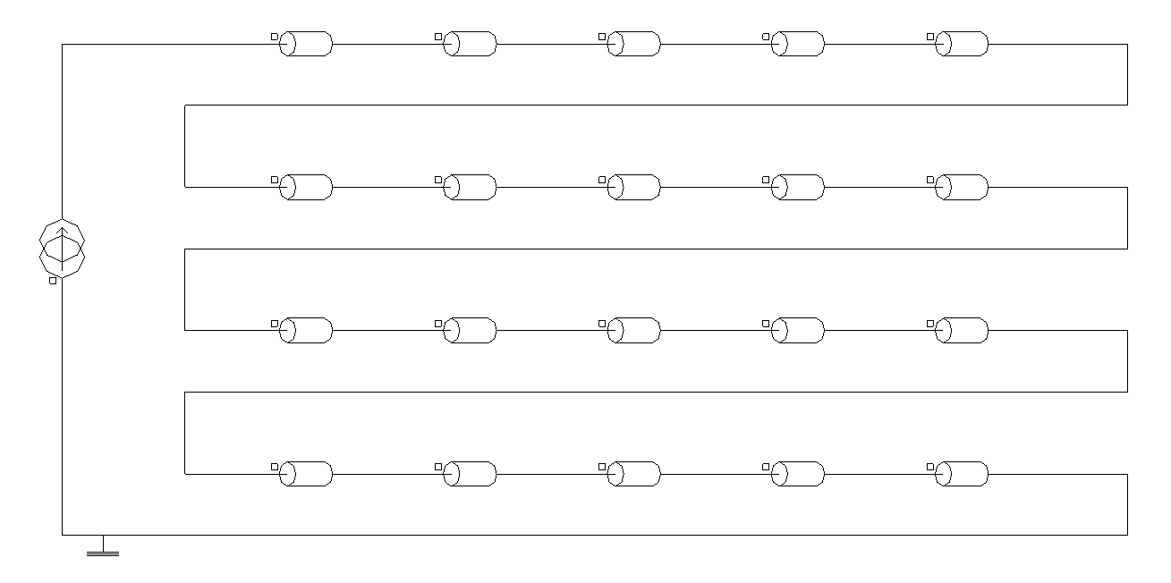
To compare the use of Solid conductor and Coil conductor regions, let us consider the modeling in Flux 2D of a hypothetical induction heating device consisting of a 20-turn coil magnetizing a linear ferromagnetic structure and a copper plate. The coil itself is formed from a copper conductor with a circular cross-section and fed by a current source at increasing frequencies.
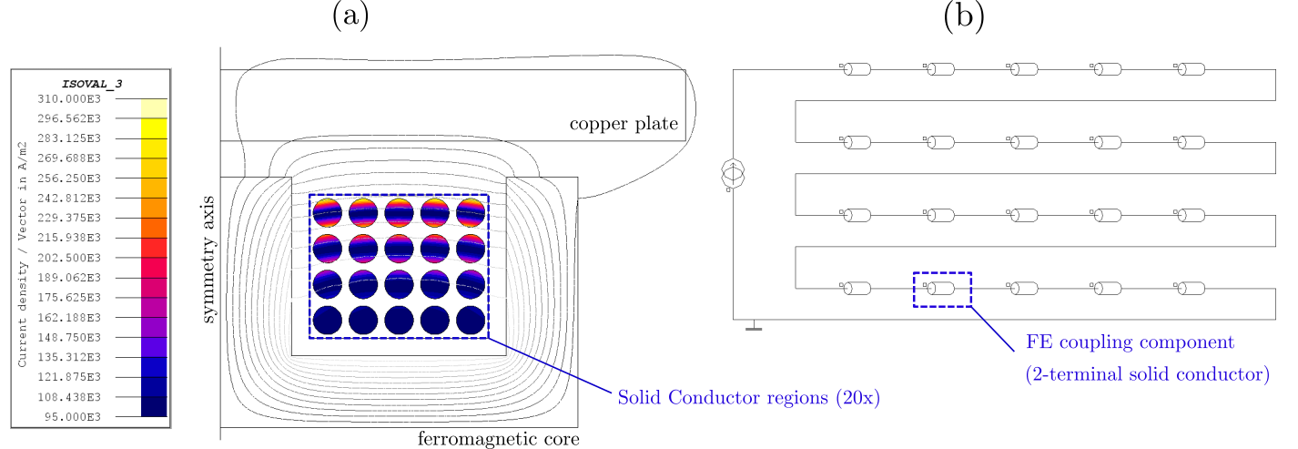
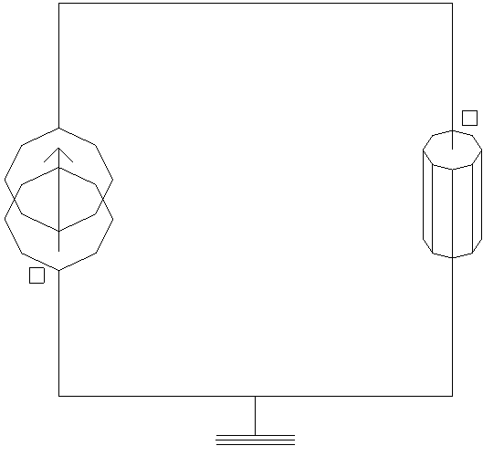
Figure 4, on the other hand, displays the same device modeled with a different approach. The twenty turns are no longer represented individually in the geometry and a single coil conductor region is assigned to a rectangular surface enclosing the winding. Consequently, only one FE coupling component (Stranded coil conductor type) is required, and both the geometry description and the representation of the external circuit become simpler.
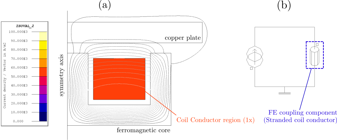
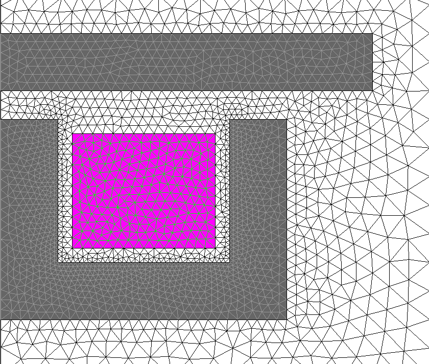
Adopting the Coil Conductor region approach also leads to simpler meshes (and consequently to smaller memory requirements and shorter computation times) as shown in Figure 5.
It should be remarked that the approach based on Coil Conductor regions gives rise to three possibilities:
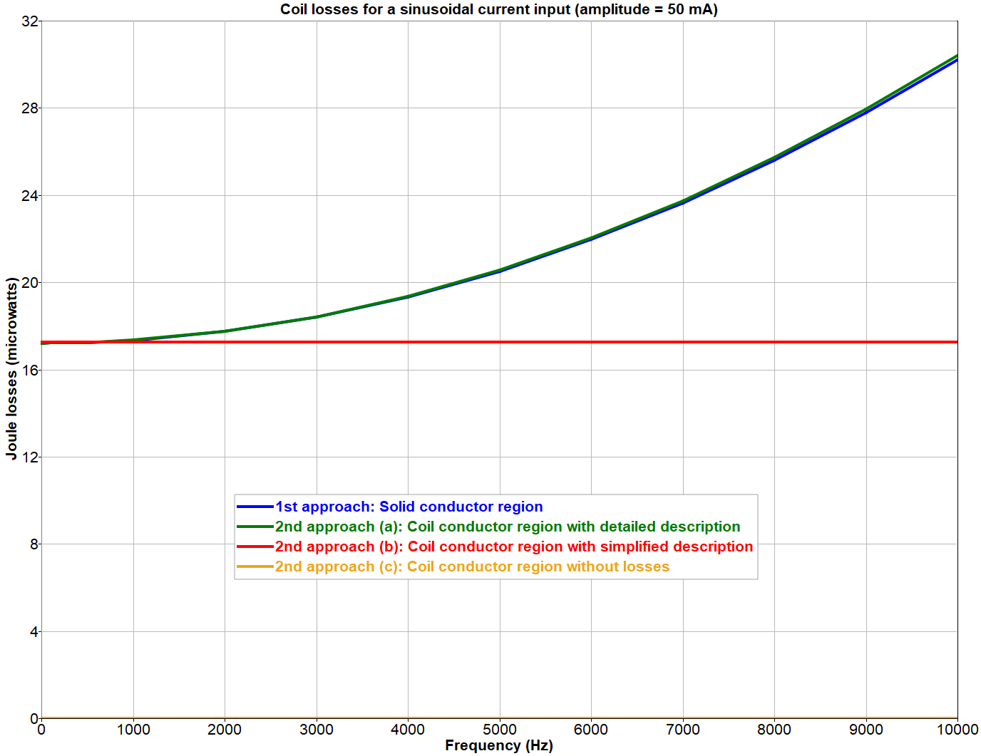
- (a) The user may provide a detailed description of the unit cell of the winding while creating the coil conductor region. This description includes parameters such as the conductor material, the number of turns, shape and dimensions of the cross section, the spacing between turns, the coil fill factor, etc. In this case, Flux applies the homogenization procedure described in the previous section and accounts for the proximity and skin effects. The losses evaluated in the coil conductor region follow the same frequency behavior predicted by the first modeling approach using several solid conductor regions, as shown in Figure 6.
- (b) The user may provide asimplified description of the winding instead, consisting only of the conductor material, number of turns, and fill factor. Under these circumstances, Flux can not perform the homogenization of the winding. Thus, skin and proximity effects in the coil are not taken into account, and the losses evaluated in the coil conductor region are only accurate for direct current or low-frequency excitations. This behavior may also be verified in Figure 6.
- (c) Alternatively, the user could provide an even more minimalist description of the winding, given only by its number of turns. The assignment of a material to the coil conductor region becomes optional and does not affect the results. This case corresponds to a perfect conductor, and the losses evaluated in the coil conductor region are equal to zero at all frequencies (represented by a constant horizontal line at zero watts in Figure 6.
Summary
| Meshed Coil region type | Current density | Mesh | Description of the coupled electric circuit | Frequency behavior of Joule losses |
|---|---|---|---|---|
| Solid Conductor | 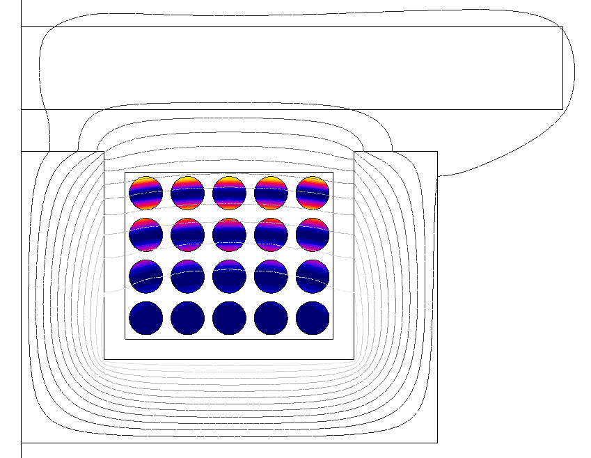 |
 Complex meshes required. |
 Potentially elaborate. One FE coupling component required for each Solid Conductor region. |
 Skin and proximity effects fully taken into account, leading to augmented Joule losses at higher frequencies. |
| Coil Conductor with a detailed geometrical description | 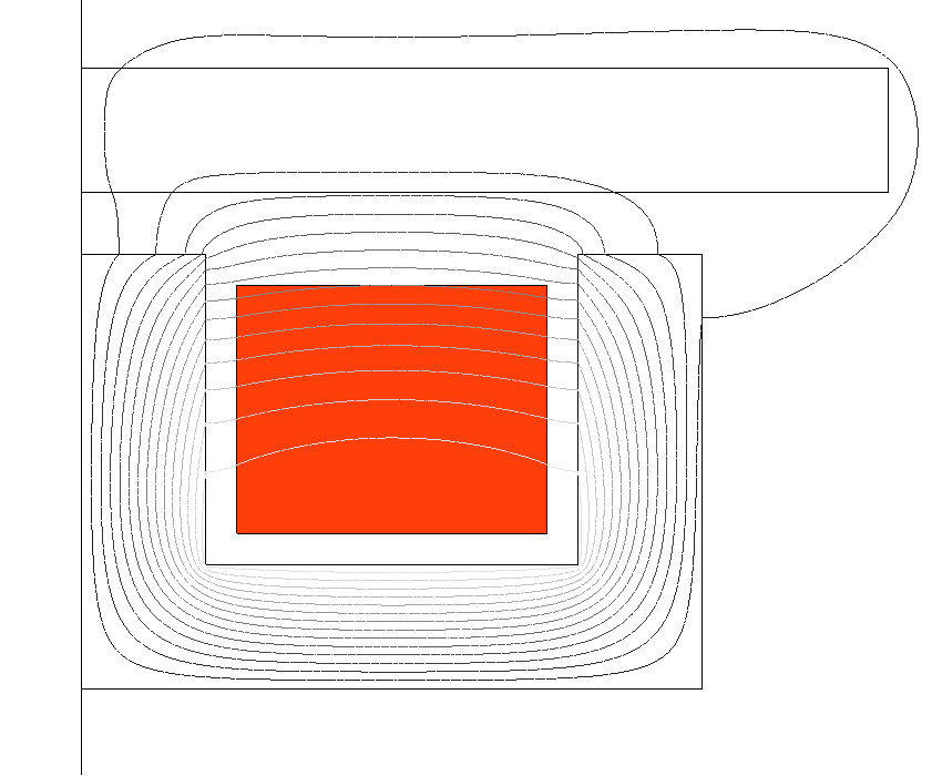 Flux evaluates an equivalent uniform current density distribution. |
 Coarser meshes are possible. |
 Straightforward. Only one FE coupling component required. |
 Skin and proximity effects taken into account by means of homogenization of the winding. Augmented Joule losses at higher frequencies as in the case of Solid Conductor regions. |
| Coil Conductor with a simplified geometrical description |  Joule losses are non-zero and constant at any frequency. Results are accurate for direct current and low-frequency excitations. |
|||
| Coil Conductor without Losses |
 Joule losses are constant and equal to zero at any frequency. |
How to Use Meshed Coil Regions in Flux
The previous sections laid the groundwork for understanding the concept of a meshed coil region in Flux. They focused on the relevant physical phenomena modeled by this region type and on comparing its derived subtypes, namely the Solid Conductor region, and the Coil Conductor region (with detailed and simplified geometrical descriptions and without losses).
For additional information on how to create and use each type of meshed coil region in Flux projects, the reader is referred to the documentation topics below:
Furthermore, for discussions on more specialized aspects of the description of a coil in Flux projects, such as the use of symmetries, the creation of FE coupling circuit components and the impact of Flux applications on coil models, the following topics are suggested:
Bibliographical references
For further reading on the skin and proximity effects, on the evaluation of losses in coils and on homogenization techniques, a list of bibliographical references is available here.