Since version 2026, Flux 3D and Flux PEEC are no longer available.
Please use SimLab to create a new 3D project or to import an existing Flux 3D project.
Please use SimLab to create a new PEEC project (not possible to import an existing Flux PEEC project).
/!\ Documentation updates are in progress – some mentions of 3D may still appear.
Composed coil
Shape and dimension
Composed coils are ones which complex shape is defined by the user.
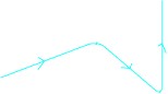
The shape of the coil is the path (open or closed) composed by a set of points. The connecting elements between the points are built on the basis of straight segments with taking into account of the curves if they exist, as presented on the figure below. A curvature radius, associated to the point, defines the curve.
|
Composed coil with closed path, described by 3 points |
Composed coil with open path, described by 3 points |
|---|---|
 |
 |
| a curvature radius R = 0 |
a curvature radius R is associated to the point P 2 |
Current direction
A coil is defined in a proper coordinate system. The direction of the current is dependent on the orientation of this coordinate system and the arrow on the image of the coil defines the direction of the positive current in the coil.
In the composed coil the direction of the current follows the succession of the points.
The user can easily change the current direction by reversing the order of the points
via the button  .
.
Sections
The types of associated sections are presented in the table below.
| Section | Composed coil |
|---|---|
|
Line *
|
 |
|
Disc (volume displaying)
|
 |
|
Disc (the mean fiber displaying)
|
 |
|
Rectangle
|
 |


Orientation of a rectangular section
For rectangular sections (sections of line or rectangle type), it is necessary to define the position of section as presented in the figure below.
The orientation of section is defined in the plane perpendicular to mean fiber

There are two different situations:
-
if a coil is formed of several not aligned segments :
the orientation is predefined and fixed by Flux
-
if a coil is formed of only one segment (or several aligned segments ):
the orientation is free and defined by the user
These two situations are detailed in following blocks.
Orientation (1)
The orientation for a coil formed of several not aligned segments is imposed by Flux. The orientation of a section is a function of the coil shape, i.e. of its segments positioning.
The user can define a rotation angle of 90° to make turn the rectangular section of 90°; but that is equivalent to swap the height and width values.
In the example below the section of rectangle type is oriented using the rotation angle.
| Rotation angle = 0° | Rotation angle = 90° |
|---|---|
 |
 |
Orientation (2)
The orientation for a coil formed of only one segment (or of some aligned segments ) is defined using an orientation vector and a rotation angle (optional) as represented in the table below.
- an orientation vector
 gives the direction of the width / thickness
of the section for an angle of 0° in the plane of the section (see figure
below)
gives the direction of the width / thickness
of the section for an angle of 0° in the plane of the section (see figure
below)
- a rotation angle α (optional) is the angle of the clockwise section rotation
in the plane of the section (see figure below)

Example of orientation
In the example below the section is oriented using:
- the
 vector to define the width (or the thickness)
position
vector to define the width (or the thickness)
position - the rotation angle equal to 0°

If the vector ![]() is not in the plane of the section, Flux projects it in
this plane.
is not in the plane of the section, Flux projects it in
this plane.
The vector ![]() should not be collinear with the segments.
should not be collinear with the segments.
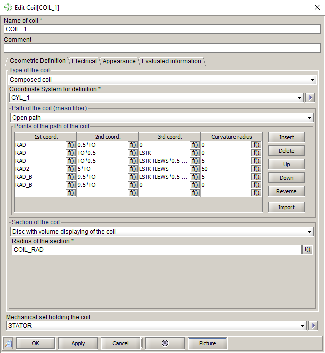
Help for creation
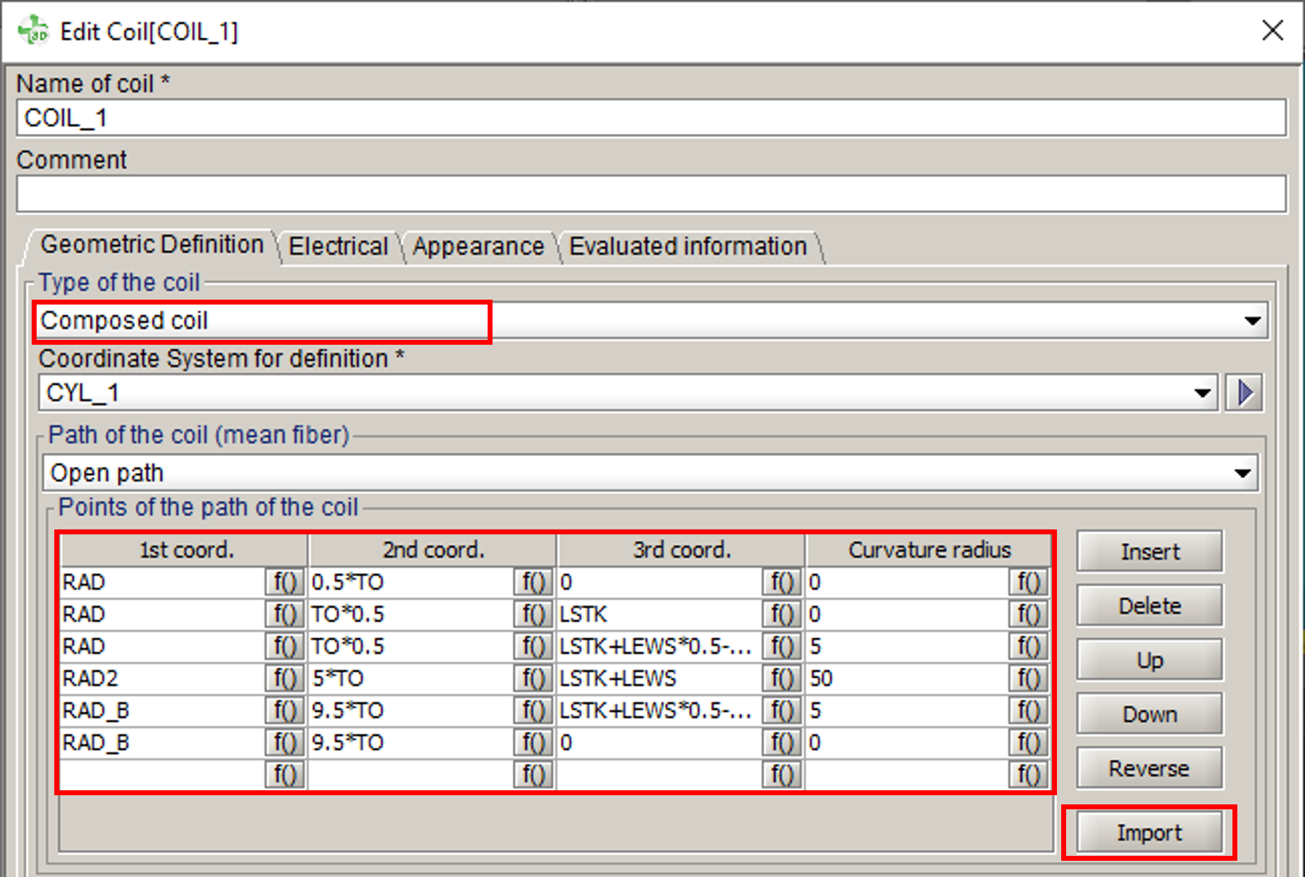
To facilitate the creation of composed coils (non meshed), several features are available in the creation dialog box :
- Insert a point in the list via the button
 .
. - Delete a point in the list via the button
 (after activating one of the cells of the
line to be deleted).
(after activating one of the cells of the
line to be deleted).The definition line of the point is fully deleted, i.e. the 3 coordinates as well as the curvature radius.
- Move a point up or down using the
buttons
 and
and  (after activating one of the cells of the line to be
deleted).
(after activating one of the cells of the line to be
deleted). - Reverse the order of the points in the table using the button
(allows, among other things, to easily change the
direction of the current in the coil).
- Import a list of points contained in a TXT
file in order to fill the points table with the desired list of points
via the button
 .
.If the table already contains points, the import will overwrite them all and replace them with the list of points of the imported file.
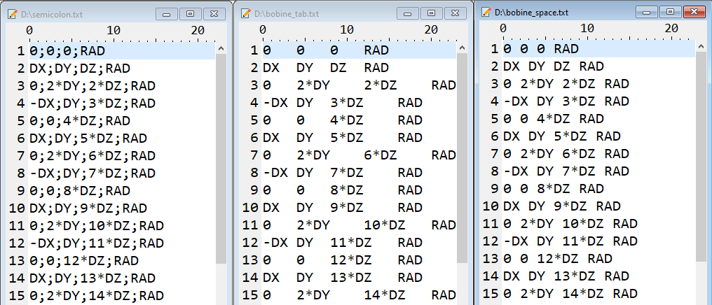
The file must contain 4 columns: the coordinates X, Y, Z and the value of the curvature radius. The separator can be:
- a semicolon
- a space
- a tabulation
Composed Coil by file import
A dedicated type is available to create a composed non meshed coil directly by importing a csv file.
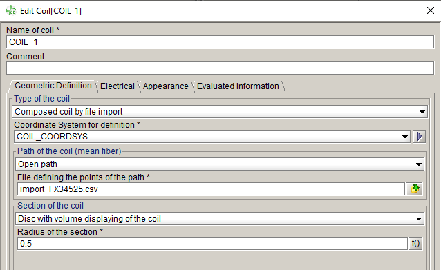
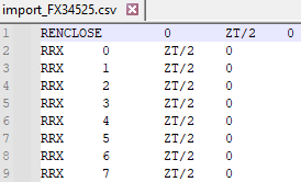
The CSV should be formatted as below:
- 1st column: X coordinate
- 2nd column: Y coordinate
- 3rd column: Z coordinate
- 4th column: curvature radius
Difference between 2 possibilities of creation by import
It exists 2 possibilities of creation of composed non meshed coil by import:
- By using the Composed coil type + using the
"Import" button to fill the table with points informations,
contained in a txt file.Tip: Recommended for few points
- By using the Composed coil by file import type, with directly
a selection of csv file, without table in the dialog box.Tip: No limit of number of points. It's recommended when a lot of points are required.
| Difference between the both possibilities of creation of non mesh coil by import | |
|---|---|
| Composed coil + "Import" button | Composed coil by file import |
| Fill the table in the dialog box
|
No table in the dialog box
|
|
Limited number of points, because there is a limitation on the number of lines of a script python when it is executed. |
No limitation of the number of points, because the python command contains only the csv file, not all the coordinates of each point. |
The corresponding python contains the list of point with X,Y,Z
coordinates and the curvature radius. |
The corresponding python contains only the csv file |