Since version 2026, Flux 3D and Flux PEEC are no longer available.
Please use SimLab to create a new 3D project or to import an existing Flux 3D project.
Please use SimLab to create a new PEEC project (not possible to import an existing Flux PEEC project).
/!\ Documentation updates are in progress – some mentions of 3D may still appear.
2D Example: Geometry and mesh tutorial
Foreword
This paragraph is a summary of cases treated in detail in the 2D example: "Geometry and mesh tutorialFirst steps in using Flux".
The files relating to the studied cases, are available in the documentation directory of the Flux DVD.
Realized study
The study proposed in the Geometry and mesh tutorial is the study of a variable reluctance speed sensor. Only the geometry model and mesh of the device are studied in this tutorial.
Studied device
The variable reluctance speed sensor consists of a cogged wheel, a magnet and a coil connected to a measuring resistance.
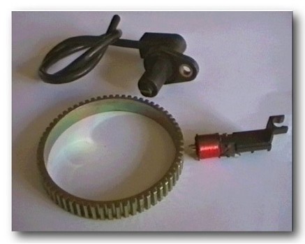
Functionality
The rotation of the target wheel near the tip of the sensor changes the magnetic flux, creating an analog voltage signal that can be recovered in probes.
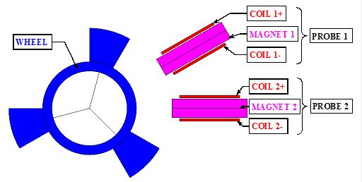
Geometric structure in Flux
The device is described in Flux as follows:
- one cogged wheel with three teeth
- two probes with a magnet and a coil around
Strategy
Two strategies of description exist:
- one-phase description:
- description of the whole device in only one Flux project
- two-phase description:
- independent description of separated parts of the device in several Flux projects
- merging the independent projects into one
The second strategy is selected in this tutorial.
Of course, the geometry can be built in ways other than the presented one. The sensor geometry is defined in this particular way in order to introduce you to the most used PreFlux features.