Altair Flow Simulator 2026 Release Notes
New Features
- Functional Mockup Unit (FMU) Improvements
- The FMU can now use the FMI version 3 standard. This allows arrays of
data to be passed between Flow Simulator and another solver. This
reduces setup time since all tube stations or segments can be selected
with one variable. Also, The FMU now uses direct calls to the Flow
Simulator functions instead of the file-based
(FS_coupling.dat) data passing in previous
versions. This should improve performance.
Figure 1. 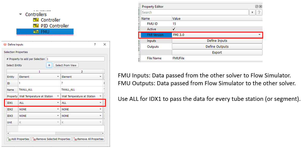
- Porous Media Tube
- The Incompressible Tube element can now use pressure drop correlations
based on the porous media theory. The pressure drop-per-length in the
tube is calculated using a viscous and inertial coefficient. These
coefficients can be input directly, or a correlation can be used based
on the media porosity and media particle diameter.
Figure 2. 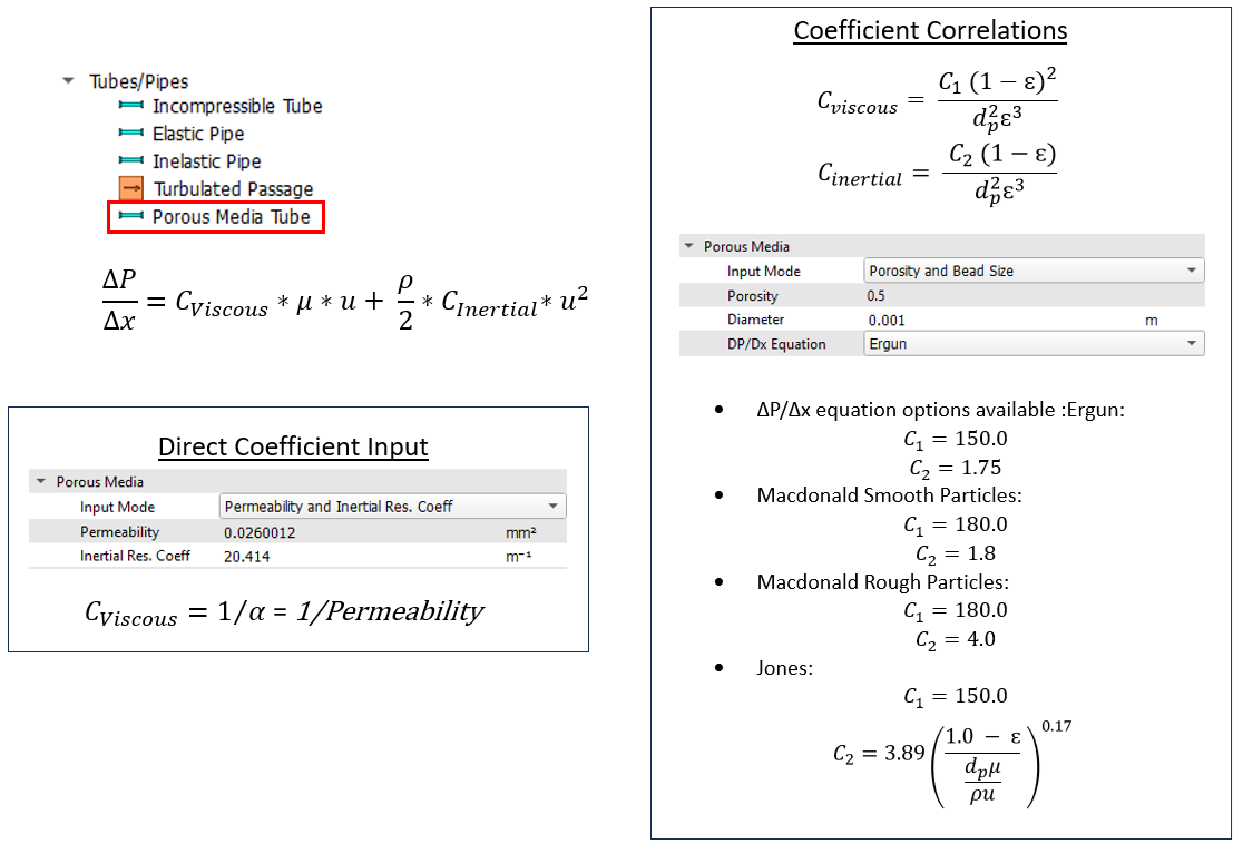
- New Flow Meter Element
- The flow meter is a flow measurement device that uses measured static
pressures to calculate flow rates through specific geometries. This
element allows systems that include these types of flow meters to easily
include the pressure drop through the device. There are four types of
flow meters included in Flow Simulator: Thin Orifice Plate, Venturi,
Nozzle, and Venturi-Nozzle. The elements can be used with compressible
and incompressible fluids. The mass flow will be limited by Mach number
≤ 1 for compressible gases.
Figure 3. 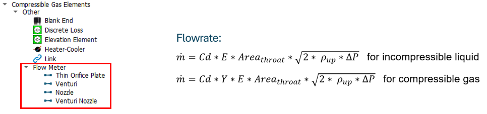
- Pin-Fin Friction and Heat Transfer Coefficient (HTC)
- Pin-Fins, like turbulator ribs, can be used to increase heat transfer,
but also increase the flow pressure losses. Friction and HTC
correlations for pin-fin surfaces have been introduced to the advanced
and incompressible tube elements. Convectors also have a new pin-fin HTC
option.
Figure 4. 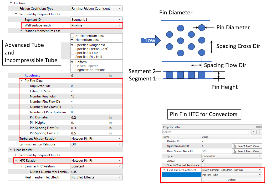
Enhancements
- Vortex Element Creation Improvements
- An option for automatic segment completion has been added to the Vortex element Property Editor to accelerate model build. This tool splits the vortex element radial extent into equal segments, create chambers, and fill tables.
- Follow these steps to use this new option:
- Create a vortex element, as usual.
- Input the number of segments.
- Check the boxes if the inlet and exit chambers are to be included as swirl chambers.
- Check the box if a cavity is to be created for each of the swirl chambers. The cavity still must be completed, but checking the box will get the process started.
- Click Execute.
- The required vortex chambers are created, and the tables are filled for the Swirl Chambers and the Radii.
Figure 5. 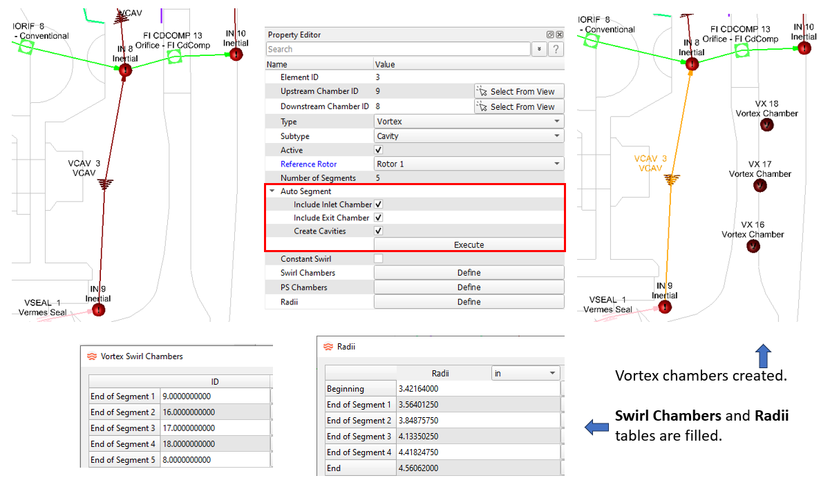
- Tube Element Conversion Improvements
- Converting an existing tube element from one subtype to another subtype will now transfer more element input data. The geometric data, end radii, number of stations, and some heat transfer inputs will be transferred from the old subtype to the new subtype. Check the converted element to verify all inputs have been transferred.
- Common reasons for tube conversions:
- Standard compressible tube to advanced compressible tube. The advanced tube has more friction and heat transfer options than the standard tube. These tubes have different convergence behavior, so switching may help solver convergence.
- Compressible tube to the incompressible tube. This change may be needed if the fluid is changed from gas to liquid. Compressible tubes with very low velocity may solve better with an incompressible tube.
Figure 6. 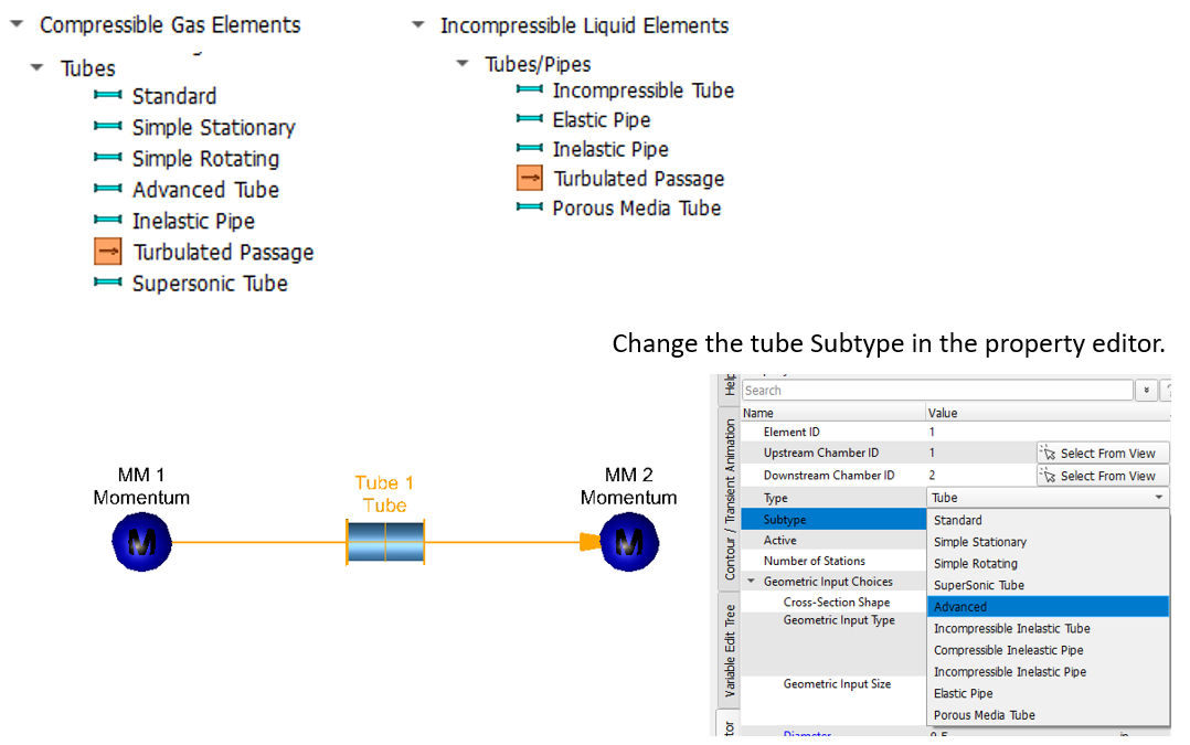
- Tube Element Split
- All types of tube elements can now be split so that a single element
becomes two elements. A new momentum chamber is created at the midpoint
of the original tube. The two new tubes have half the length and half
the number of stations as the original tube. Some inputs, such as
complicated geometry, may need to be redone on the new tubes. Verify the
inputs.
Figure 7. 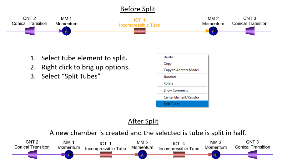
- Norris Rough Tube HTC Correlation
- A new duct flow correlation based on a reference from Norris is
available for tube elements and convectors. This correlation is for
rough walls. It is similar to the Gnielinski correlation but will use a
different approach to account for roughness. The Gnielinski correlation
just uses the friction factor for the rough wall in the Nusselt number
equation. The Norris correlation will use a smooth wall friction factor
in the Nusselt number equation and a scale factor to account for the
roughness.
Figure 8. 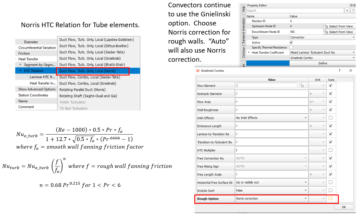
- Area Calculation Option for Fin Heat Transfer Coefficient (HTC)
- There are two HTC correlations for a surface with rectangular fins that
are available for convectors. There are a free convection and a forced
convection (Heiles) correlation. Previous Flow Simulator versions
calculated a convector surface area based on the geometric inputs for
the correlation. An area calculation option has been added to the inputs
for these two correlations. You can choose to use the surface area based
on the correlation inputs or use the surface area from the convector
resistor input.
Figure 9. 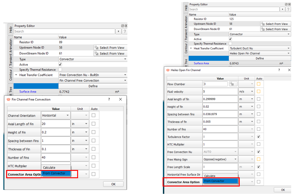
- Slot Effects for the Taylor Rotating Gap HTC
- The Taylor rotating gap HTC correlation that can be applied to
convectors will now account for slot (saliency) on the rotor or stator
surface. An HTC multiplier will be calculated based on the gap geometry
and the Taylor number. In-house CFD studies, as well as trends in other
references, were used to determine the multiplier to the smooth surface
HTC.
Figure 10. 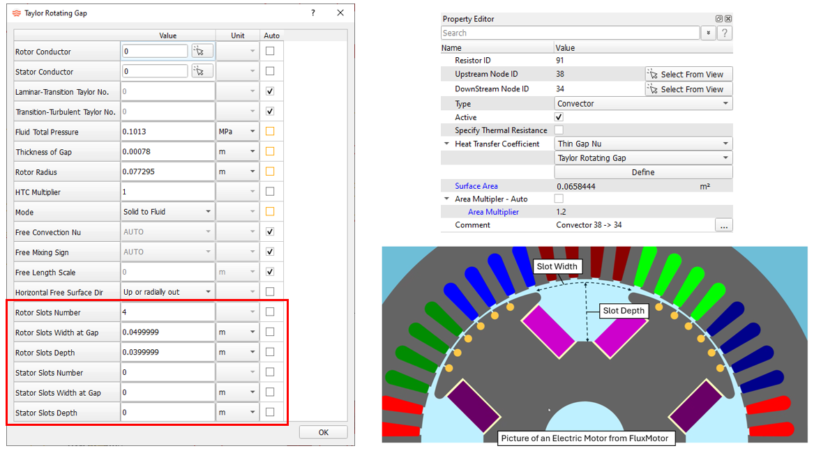
- Generic Fixed Volume (GFV) Accumulator Heat Addition
- The GFV accumulator now has input for simple heat addition.
Figure 11. 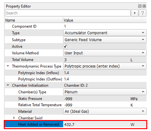
- Cylinder Component Improvements
- Several improvements have been made to the cylinder component.
- These include:
- Addition of controller gauge and manipulated variables.
- Check that the piston initial position is consistent with spring and pressure forces.
- More cylinder results in the .res file.
- Improved solver robustness.
Figure 12. 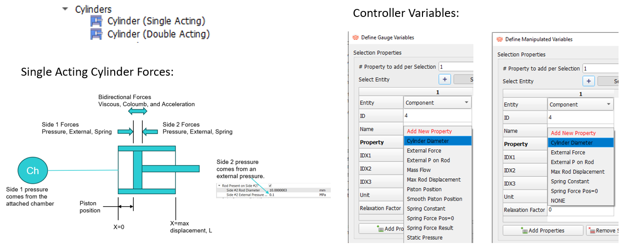
- Radiator Emissivity Options
- The radiator resistor can now use the material properties for the
surface emissivity. Previous versions only allowed a numeric emissivity
input.
Figure 13. 
- Mission Data Fill Improvements
- Two new customizable options for entering mission data are available.
Both options require the usual mission data table to be filled with
parameter names that are needed for model setup. The numbers in the
table will be replaced by the two new options. This can be useful if the
mission data file format is not compatible with Flow Simulator.
- A new subtype in the Customization Manager called Mission_Input. A Python script for a Fortran subroutine can be written to fill the mission tables. A sample Fortran subroutine (CUSTOM_MISSION_INPUT) can be found in <FlowSimulator_install_folder>\Resources\Customize\fs_custom_lib.f.
- A new API function called FS_SET_MISSION (_C for C++). A sample can be found in <FlowSimulator_install_folder>\ Resources\Customize\Solver_API_Examples\CPP\transient\2_set_mission.7z and …Fortran\transient\2_set_mission.
Figure 14. 
Resolved Issues
The following Solver issues have been fixed:
- Fixed the heat transfer limit for chambers with an attached convector and another heat source (like cavity windage). This can change temperature results for chambers with a fluid temperature entering the chamber that is very close to the convection wall temperature. This problem did not affect vortex chambers.
- The Area Multiplier was being ignored for convectors using a specified thermal resistance. The area multiplier is now used in the heat transfer equation. This will affect thermal model results if the model uses a specified thermal resistance on a convector and the area multiplier is not 1.0. It will not affect results for the typical convector input of a heat transfer coefficient and an area.
- A boundary chamber using the Calculated, Enter Initial Guess option for the Swirl can have problems if the flow enters the boundary chamber for some iterations during convergence, then flips so all flow exits the chamber. The swirl will remain at the value from the reversed flow condition. This is now fixed, although it is recommended the Fixed swirl option be used instead of the Calculated, Enter Initial Guess option if no flow enters the chamber.
- Boundary chamber initialization has been changed so that the user-supplied swirl is used to calculate the chamber Mach number and total pressure for each time step for source chambers (all flow exiting the chamber). Previous versions did not recalculate a chamber Mach number for each time step. This should have minimal effect on overall model results since the static pressure is often used for boundary chambers with swirl.
- The chamber radius is determined from the elements attached to the chamber. Previous versions ignored the radius of stationary conventional orifice elements. The new release will consider the nonzero radius of a stationary orifice when determining the chamber radius. This change should not affect results of properly defined models. Results may change if the radius of a stationary orifice is not defined properly relative to the other elements attached to the chamber.
The following GUI issues have been fixed:
- Initializing with results will now update the vortex chamber information (pressures, temperatures, and swirls). Previous versions updated all chamber types except for the vortex chambers. If a chamber does not exist in the results file, the GUI will not change the pressure and temperature. Previous versions would change the pressure and temperature to 0.
- Vortex radii are now stored more accurately in the .flo file.
- The active/inactive status of cavity flows are now changed based on the status of the element.
- The adiabatic run option under “Additional Analysis Controls” is now writing the correct data to the .flo file for option 2 - All items adiabatic.
- A user-defined gas will not be available when creating an emulsion mixture.
- Duplicate cavity surface after moving surface points.
- Scrollbar missing in the Solver Run window.
- View fitting that ignores the CAD geometry now works. The GUI will open a model and return the view to the saved state.
- Large model speed improvements for opening and viewing.
- Group line visibility problems.
- Deleting mission column corrupted the mission window.
Known Issues
The following known issues will be addressed in a future release as we continuously
improve performance of the software:
- Visibility of some items in dark mode will be improved in future releases.
- The post-processing for “Group Heat Flow” may not sum the heat flows correctly for complex groupings.