Altair Flow Simulator 2025 Release Notes
Highlights
- Flow Simulator API
- GUI dark mode
- Solver accuracy improvement for real gasses
New Features
- Flow Simulator API
- The Flow Simulator solver can now be run from a user-defined program using a set of functions to load and run a Flow Simulator model. A dynamic link library (DLL) file containing the Flow Simulator solver can be linked to a user-defined program. Several simple functions are available so that the user-defined program can interact with the Flow Simulator model: FS_LOAD_MODEL, FS_RUN_MODEL, FS_GET, FS_SET, and FS_END. C, C++, and Fortran programing languages have been tested and examples are supplied with the Flow Simulator installation (<install_directory>/FlowSimulator/Resources/Solver_API_Examples).
- GUI Dark Mode
- The Flow Simulator GUI display can be toggled to dark mode. The dark mode
uses a black background with lighter text colors.
Figure 1. GUI Dark Mode 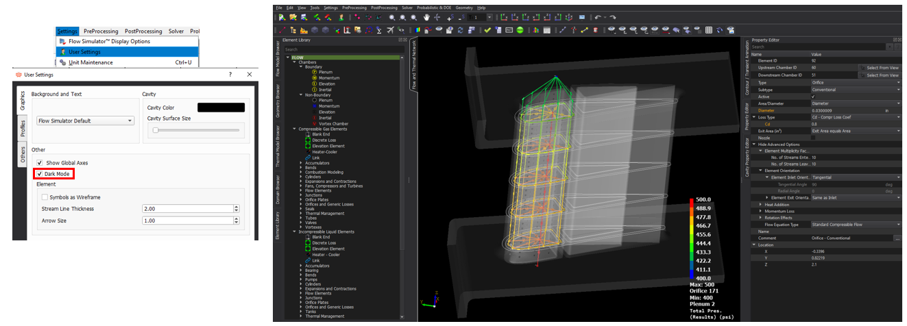
Enhancements
- Solver Accuracy Improvement for Real Gasses
- Since version 2022, Flow Simulator has used the compressibility factor, z, to adjust the ideal gas relationship for density. The compressibility factor improves the accuracy for fluids that are at pressures and temperatures where they do not behave like an ideal gas.
-
Figure 2. Real Gas Gammas 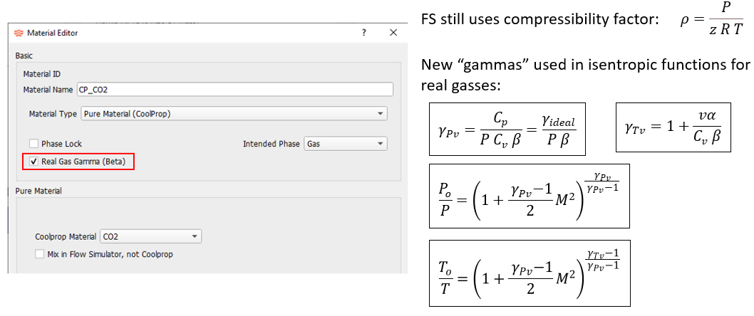
- Text Magnified During Hover
- An object’s text can be magnified temporarily when the mouse pointer is on
the object. This is useful if the text size is too small to read at the
current zoom level or model scale. You can toggle this behavior in the User
Settings.
Figure 3. Text Magnified During Hover 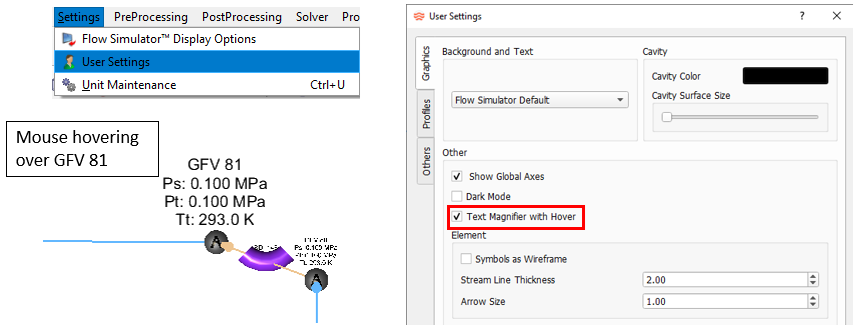
- Fan, Compressor, and Turbine Efficiency Calculations
- The total temperature exiting a fan, compressor, or turbine is a function of
the total pressure change and polytropic efficiency of the component. The
calculation methods have been updated to consider real gas effects. If real
gas effects are required, the Schultz or Small Step method should be used
for an accurate exit temperature. The Small Step method is the most accurate
but can also increase solver run times. The Schultz method is less accurate
but is fast. The “Auto” method is the default. It uses the standard ideal
gas equations for ideal gasses and the Schultz method for real gas. Coolprop
must be the fluid property source for the Schultz and Small Step
methods.
Figure 4. Fan, Compressor, and Turbine Efficiency 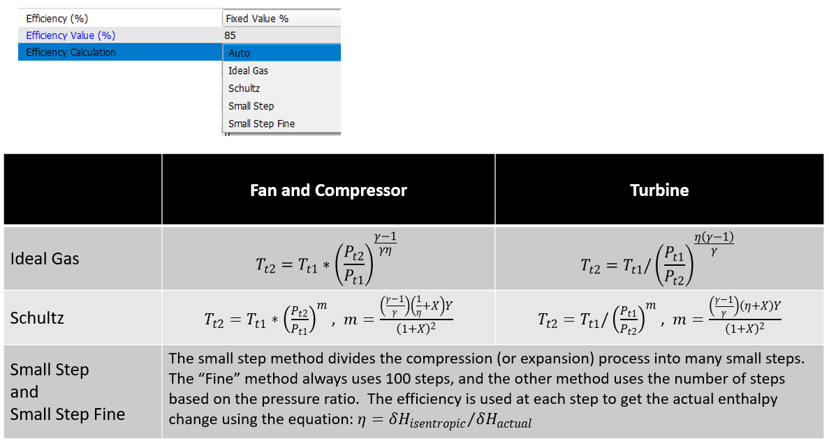
- Heat Transfer Coefficients (HTC) for Rotating Cavities
- Four new HTC correlations for rotating surfaces have been added. These
correlations are useful for rotating machines such as gas turbines and
electric motors.
- Rotating Cavity Using Duct Flow: Uses the Dittus-Boelter duct flow
correlation for general cavities with rotating flow and surfaces.
Figure 5. Rotating Cavity Using Duct Flow 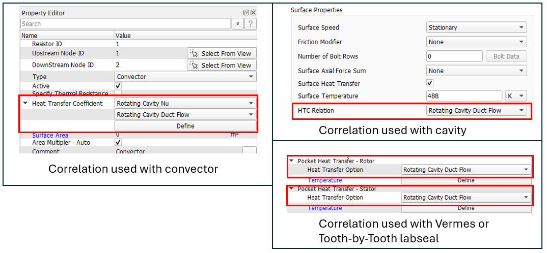
- Rotor Disk with Bore Flow: Correlation for cavities typically found
in gas turbine compressors. Use correlation on rotating disk
surfaces with axial flow at the bore. The correlation can be used
with convectors and is based on the paper by P.R. Farthing.
Figure 6. 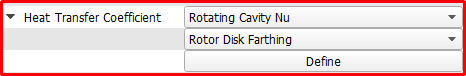
- Free Rotating Disk: Use this HTC correlation on an isolated rotating
disk. An isolated disk has no through flow, other than the flow
induced by the disk rotation, and the far field ambient fluid has no
swirl. The correlation can be used with convectors.
Figure 7. 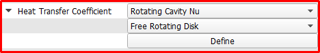
- Free Rotating Cylinder: Use this HTC correlation on the inner or
outer surface of a rotating cylinder. The correlation can be used
with convectors.
Figure 8. 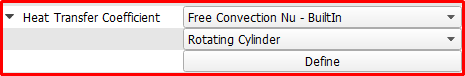
- Rotating Cavity Using Duct Flow: Uses the Dittus-Boelter duct flow
correlation for general cavities with rotating flow and surfaces.
- Thermal Node and Flow Chamber Rotor Index Color Plot
- From the GUI, you can now plot color contours of the Rotor Index for thermal
nodes and flow chambers. From the color contour panel, use the
Rotation Rotor Index option. Use this to quickly
check model inputs.
Figure 9. Rotor Index Color Plot 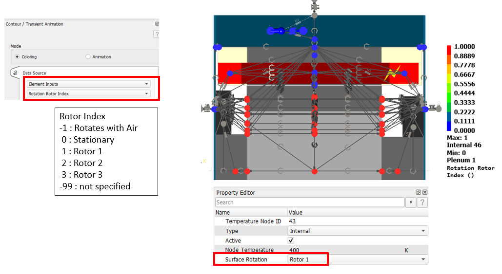
- Color Cavity Surface by Force Direction
- From the GUI, you can now color the cavity surface lines by the force
direction. Use this to quickly check the surface axial force direction
input.
Figure 10. Color Cavity Surface by Axial Force Direction 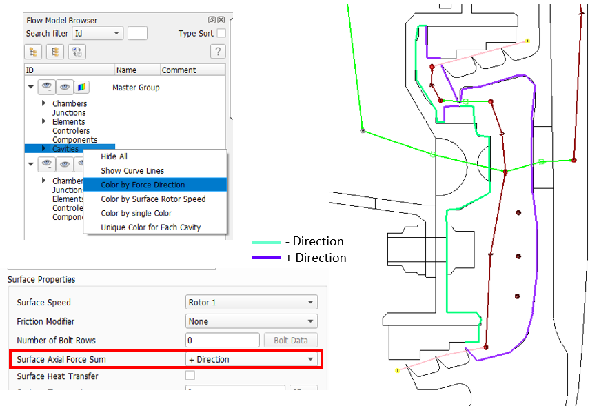
- Advanced and Incompressible Tube - New Inlet Head Loss Options
- The advanced and incompressible tube elements now have head loss options for
abrupt transition, rotating annulus, and rotating parallel tube. You can
combine the abrupt transition loss with the rotating annulus or rotating
parallel tube.
Figure 11. New Inlet Head Loss Options for the AT and IT 
- Advanced Tube - New Friction Option
- The advanced tube has a new wall friction option for a rotating tube that is
offset and parallel to the rotation center line. It is based on a paper by
Johnson.
Figure 12. AT new Friction Option 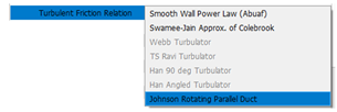
- Automatic Area Option for Several Elements
- The amount of user input has been reduced by introducing an automatic area
option for several elements. This option only works if an element is
attached to a single element upstream and downstream that has a specified
geometry (area or diameter). Two elements that use the automatic area option
cannot be attached to the same fluid chamber. The automatic option is now
the default for these elements. The areas are extracted at solver run time.
Check the *.res file for areas used for the
element.
Figure 13. New Automatic Area Retrieval Options 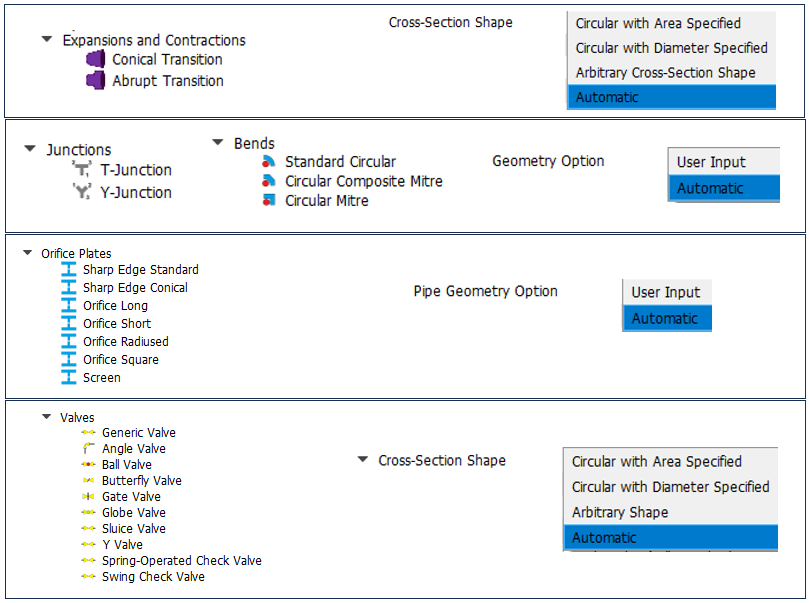
- Orifice Plate Element Grill K Loss
- New K loss options have been added to the Screen subtype of the orifice
plate element. These options use a K loss based on the ratio of the free (or
open) area to the pipe area. The losses are different if the grill is at the
inlet (from ambient to the pipe) or the exit (from the pipe to ambient).
Figure 14. Grill K Loss for Orifice Plate Element 
- Automatic Flow Equation (Fluid) Type for Element
- Most elements have flow equations for compressible gas and incompressible
liquids. The type of equation used can now be automatic and based on the
fluid entering the element. Compressible gas elements are used for gases
such as air, while the incompressible liquid options are used for liquids,
such as water. The benefit of the automatic option is for models that may
have phase change or if the fluid phase is not known before the run.
Elements with the automatic flow equation option include: valves,
transitions, bends, junctions, elevation, and orifice plate.Note: The orifice elements automatically use incompressible equations if a liquid is entering the element.
Figure 15. 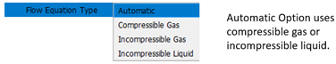
- Generic Fixed Volume (GFV) Accumulator Improvements
- Two changes have been made that make it easier to use GFV accumulators to
represent the fluid volume of piping systems for transient analysis. The
first change is the option to convert a momentum chamber to a GFV. The
automatic element creation tool creates momentum chambers. The new change
makes it easy to convert these to GFV. The second change is the option to
use the volume of the attached elements instead of a user-supplied volume.
This option uses half the volume of all elements attached to the GFV. Only
elements that have geometry information to calculate a volume are valid:
tubes, conical transitions, and bends. The *.res file
contains the volume found in the attached elements.
Figure 16. GFV Accumulator Improvements 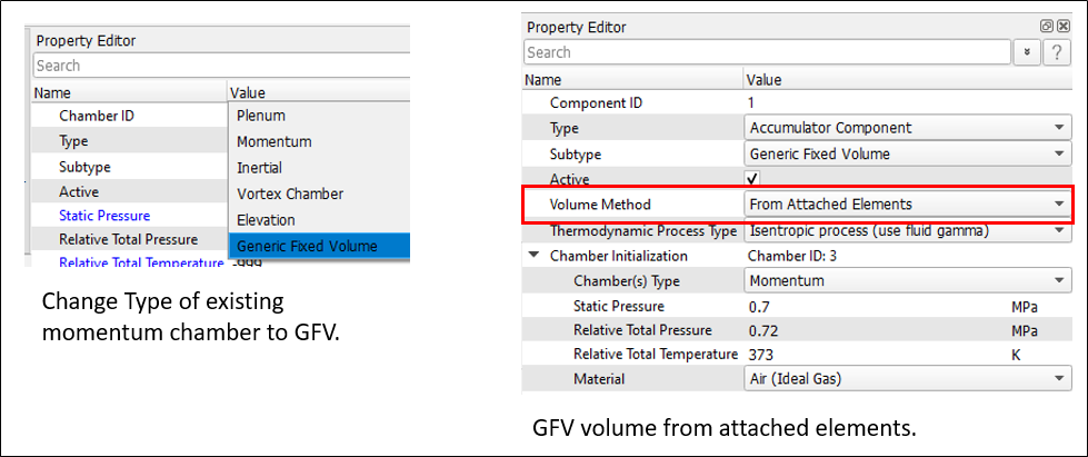
- Element and Resistor Connections
- Version 2024.1 introduced the option to change the element and resistor
connection chambers (and nodes) in the Property Editor. Now, the connecting
chambers (and nodes) can be selected from the modeling window.Note: The Element Connections tool will be deprecated in the future.
Figure 17. Element and Resistor Connection Edits 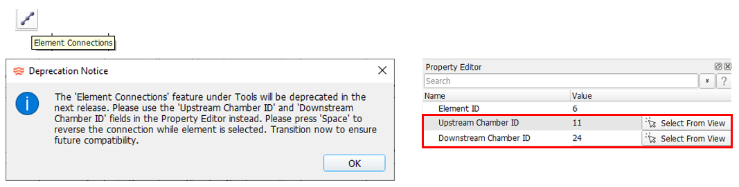
Known Issues
The following known issues will be addressed in a future release as we continuously
improve performance of the software:
- Some very large models or models using a small screen unit (like millimeters) can have text that is too small to read. The maximum size of 80 may be too small. Using a different screen unit may allow for larger text.
- Visibility of some items in dark mode will be improved in future releases.
Resolved Issues
- GUI problem with the tube element bend table always changing to four bends when edited.
- GUI crash in the Customization Manager.
- Problems with the GUI Goal Seek tool not using the number of streams when using flow rate as the target.
- GUI problem for controllers using linear relationships.
- GUI problem when copying items that are in a flow group.
- GUI problem when creating elements directly from geometry. The GUI creates less short tube elements and uses the screen unit for radius limits.
- GUI now sets the screen unit to the unit of the geometry file when reading for the first time.
- The GUI text for the vortex element flow flag is now more descriptive for the option that uses another flow element.
- GUI problem with the arrowhead sizes after multi-editing resistor connections.
- GUI problem with the defaults for drop-down lists in the Analysis Controls.
- GUI problem with units of Tube Station coordinates.
- Updated Coolprop from version 6.4.3 to version 6.6.