Altair Flow Simulator 2022.1 Release Notes
Highlights
- Improved Controller user interface.
- Added units capability to the Variable Editor.
New Features
- Improved Controller User Interface
- The user interface for mission and feed forward controllers has been improved. The new interface uses a table-type input structure that simplifies controller creation.
-
Figure 1. Property Editor for New Controller 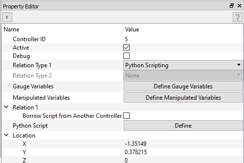
Figure 2. Table Input for Controller Gauge and Manipulated Variables 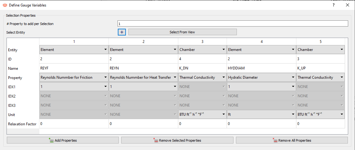
- Units Capability Added to the Variable Editor
- The Variable Editor has units’ information so you can define variables in units other than the standard Flow Simulator (English) units. For example, you can now define pressure in MPa, while previous versions required pressure to be defined in PSI. Variables from existing models do not have any unit information until they are input. The user interface displays a prompt if the Unit Type is inconsistent with the units needed by the element or chamber using the variable.
-
Figure 3. Variable Editor with New Unit Information 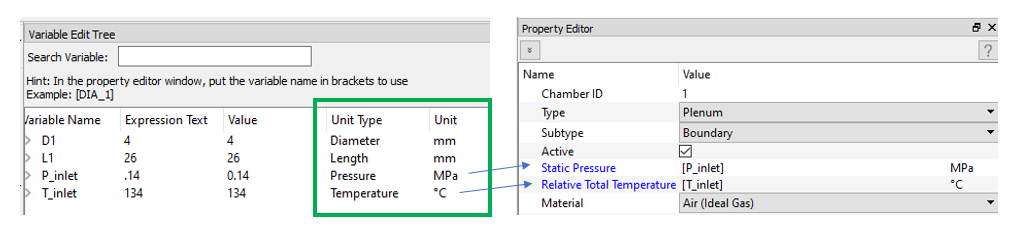
- Coolprop Incompressible Liquids
- From Flow Simulator, you can access a new set of incompressible liquids from Coolprop. These fluids include pure substances (for example, Water, DOWTHERM) and aqueous mixtures where the mass fraction of water can be adjusted (for example, Ammonia, Ethylene Glycol, Propylene Glycol). More information is available at: http://www.coolprop.org/fluid_properties/Incompressibles.html.
-
Figure 4. Coolprop Incompressible Liquids 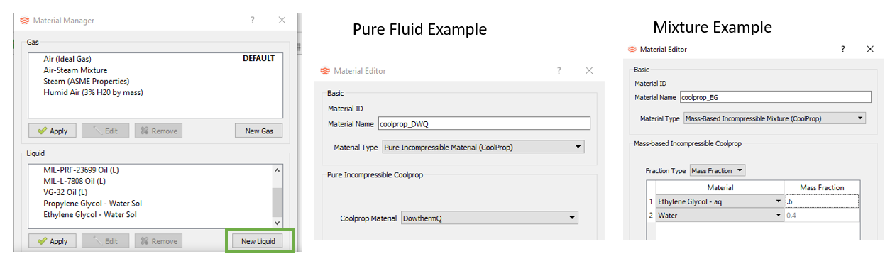
Enhancements
- Cavity Surface Simple Convection Heat Transfer
- You can add simple convection heat transfer directly to a cavity surface. A Heat Transfer Coefficient and surface temperature are input. The heat due to the convection is applied to the fluid chamber associated with the cavity. The *.cav.out file contains detailed results.
-
Figure 5. 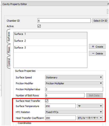
- Thermal Node Associated with a Cavity Surface
- If the cavity surface temperature is not known and needs to be calculated, use a thermal network for cavity surface heat transfer. Attach a convector(s) directly to a fluid chamber. If the fluid chamber is associated with a cavity, the thermal node attached to the convector can be associated with the cavity surface. The convector uses the cavity surface area and rotation for the heat transfer calculation.
-
Figure 6. Associate a Thermal Node to a Cavity Surface 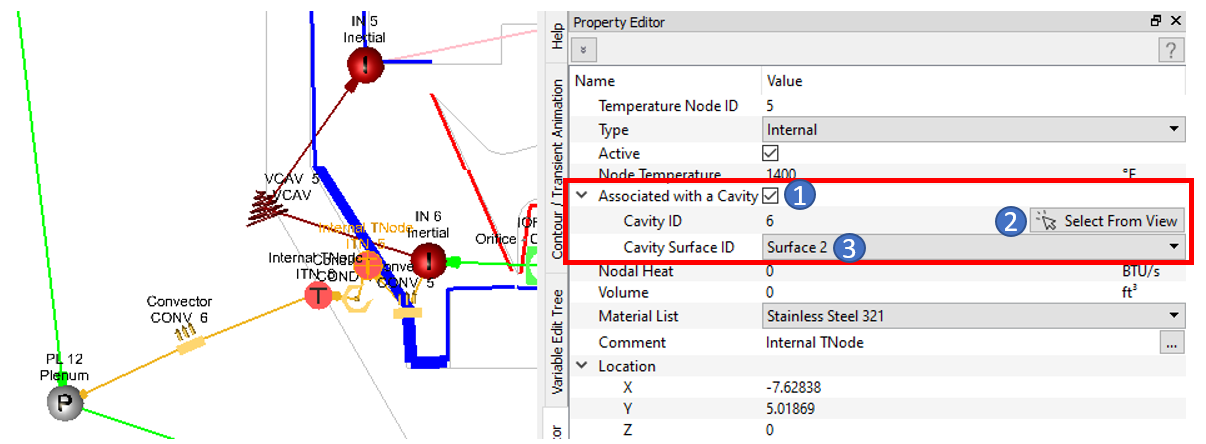
- Cavity Surface Axial Force Accounting
- Use the air pressures and radii of the cavity surfaces to calculate an axial force on each cavity surface. These forces can be used for “rotor thrust” calculations. This is just a post-processing calculation and does not have an affect on flow solver results. The only input required is the direction of the force. If force direction is “None”, the force is not calculated for that surface. The results are written at the bottom of the *cav.out file.
-
Figure 7. 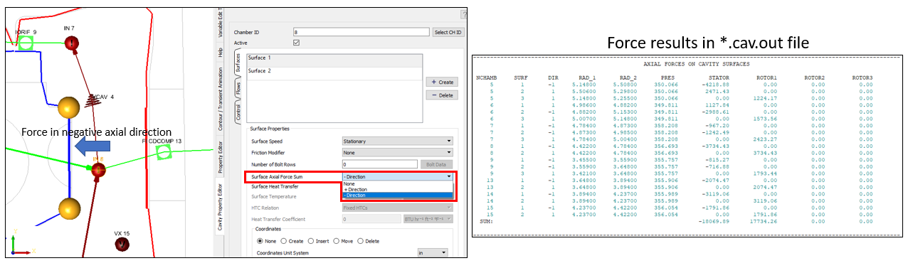
- Labyrinth (Vermes) Seal Element Simple Convection Heat Transfer
- Add simple convection heat transfer directly to a labyrinth seal pocket
surface. A Heat Transfer Coefficient and surface temperature are input.
The heat due to the convection is applied to the element at each pocket.
The Heat Transfer options are:
- None (default)
- Constant HTC
- Constant Heat Load
- Custom correlation using the “ROTATING_CAVITY_NU” subtype
-
Figure 8. 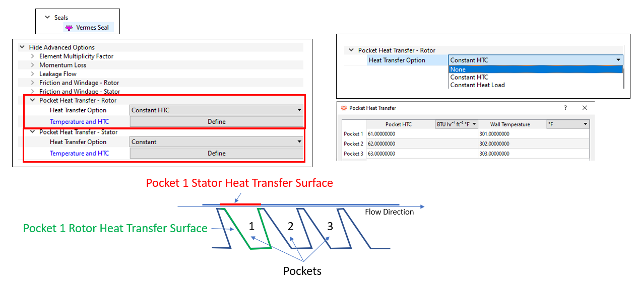
- Improved Coupling with Altair HyperStudy
- Use HyperStudy with Flow Simulator to run complex parametric studies, DOEs, and optimizations. The HyperStudy 2022.1 release automatically reads the FS_coupling.dat file and uses the lines with “FROM_FS” as input variables and the lines with “TO_FS” as output responses. This feature reduces study setup times and allows for Flow Simulator model changes to be used in existing HyperStudy studies without reparameterizing the .flo file.
- Add Exit Radius to the FI Cdcomp Element
- The FI Cdcomp element now has an input for exit radius. For models
created in previous versions, the exit radius is set equal to the inlet
radius. If the element exit radius is different than the inlet radius,
the element calculations account for the following:
- If the hole is rotating, temperature change in the element due to forced vortex pumping.
- If the hole is rotating, pressure change in the element. The upstream pressure and downstream pressure are adjusted by the pumping pressure ratio.
- If the hole is rotating or stationary, and the flow is reversed through the element, the exit radius is used as the inlet radius to determine the flow incidence angle.
- Add Fluid Quality Capabilities (BETA Release)
- Some fluid quality and 2-phase capabilities have been added to Flow Simulator. These are considered a BETA release since more testing and additional capability is needed to make Flow Simulator fully capable for 2-phase flows. Fluids must be from Coolprop, and the Energy Balance option must use enthalpy for 2-phase calculations to work. The new features include the ability to set a fluid quality for boundary chambers. The boundary chamber pressure and quality is used to set the chamber temperature. Another new feature is the ability to set fluid quality targets at the exit of some elements. These elements calculate the heat added or removed to achieve the desired fluid quality.
-
Figure 9. New Quality-related Inputs for Boundary Chambers and Elements 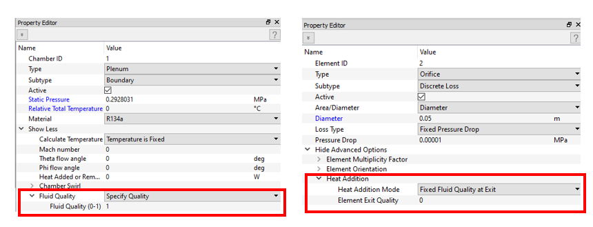
- Add Coolprop Fluid Phase Lock Input
- A new input to specify an intended phase and to “Lock” this phase has been added to Coolprop fluids. The intended phase is used by the GUI to categorize the fluid in the Material Manager. If Phase Lock is selected, Coolprop is given instructions to limit phase checking to the intended phase. This helps some models run faster, but it should have no effect on results if the fluid pressure and temperature are appropriate for the intended phase. The new Coolprop incompressible liquids are always a liquid, so they do not need this phase lock input.
-
Figure 10. Phase Lock and Intended Fluid Phase 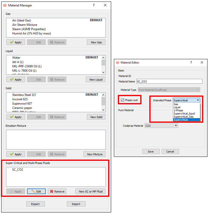
- New Controls for Temperature and Pressure Limits
- The temperature (or enthalpy) and pressure sent to the fluid property
routines must be within reasonable limits. In particular, Coolprop
returns an error if the inputs are outside of its limits. Previous Flow
Simulator versions performed checks automatically on limits, but this
did not work in all cases. The two new inputs are:
- Check Limits Option:
- Automatic Limit Checks – default and similar to previous versions
- Use Fluid Chamber P and T Limits
- No Limit Checking
- Converge Limits Option:
- Do not converge if outside limit – default and similar to previous versions
- Ignore limits for convergence
- Ignore limits after % max iteration
- Check Limits Option:
-
Figure 11. P and T Limits Used for Fluid Property Retrieval 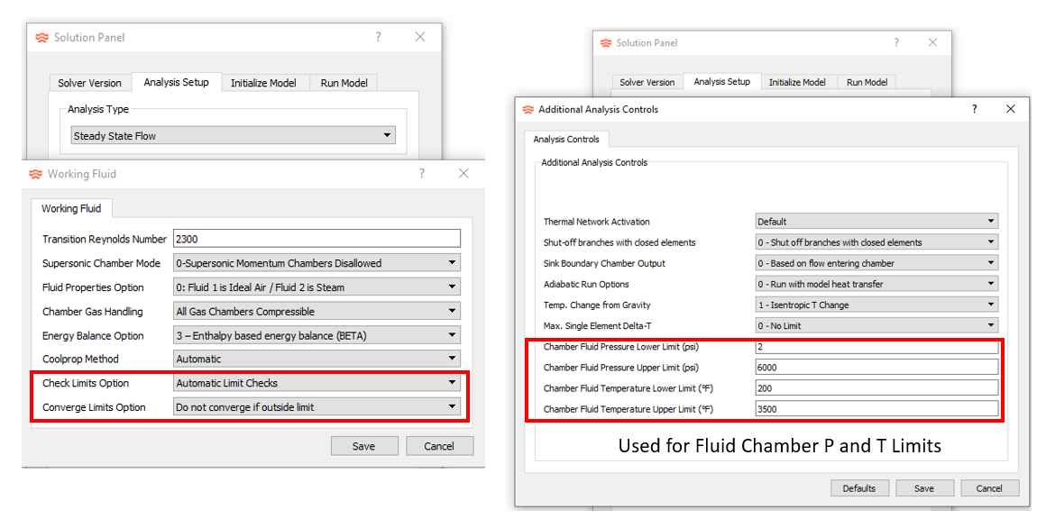
Known Issues
The following known issues will be addressed in a future release as we continuously
improve software performance:
- The new controller interface does not work with controllers that have two relations. For example, a 1D table and a Python script in the same controller.
Resolved Issues
- Limiting enthalpy change during iterations to avoid nonphysical results during convergence.
- Solver calculates the swirl on a boundary sink chamber based on elements entering the chamber. This is similar to how temperature is calculated on boundary sink chambers.
- The color contour plot of inputs works for orifice diameters and radii of various elements.
- Removed the exit radius from the fixed flow element Property Editor.