Altair Flow Simulator 2023.1 Release Notes
Highlights
- Thermal Network Grouping in the GUI.
New Features
- Thermal Network Grouping in the GUI
- Thermal entities can now be grouped to enhance model visualization and
organization. The groups can be named and colored. All entities
displayed within the group can also be colored with the group’s color.
Currently, this is only for thermal entities but will be available for
flow entities in the future.
Figure 1. Thermal Network Grouping 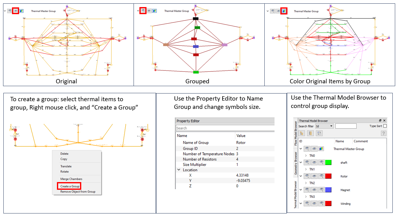
Enhancements
- Additional Heat Transfer Coefficient Correlations
- Three additional HTC correlations are available to use with convection resistors in the thermal network. These new correlations can be used for convectors not associated with a tube element.
- Combustion Element Flow Calculation
- In previous versions, the combustion element always used a flow
calculation based on the Rayleigh equations for frictionless flow with
heat addition. The Reyleigh equation captures the pressure change due to
the combustion in the element. The pressure change is not always
important, and the Rayleigh equations can have convergence problems. New
flow calculation options have been added that do not capture the
pressure change due to combustion but are more robust. The new options
use an orifice flow function calculation or attached elements to
determine the flow rate in the combustion element.
Figure 2. Combustion Element Flow Options 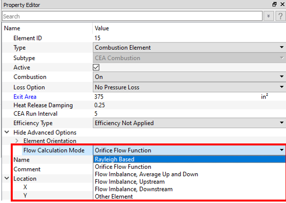
- New Controller Entity Options: Controller and Stored
- Controllers can now store data in a gauge or manipulated variable.
Controllers can also retrieve data from another controller. These new
options are useful for complex controllers that require multiple
relations (for example, a 1D table and Python). They can also help to
post-process data before sending to FS_coupling.dat
or an FMU (for example, the average the temperature of several chambers
using a Python controller).
Figure 3. New Controller Entity Option Examples 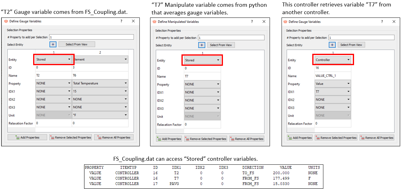
- New Controller Relation: Mission Transfer
- The controller now has a simpler method to transfer data from a mission
directly to a model item (like a valve opening). This new method is
easier than having a controller with a Python script to transfer a gauge
variable from the mission to a manipulated variable. A controller using
Mission Transfer only needs the
“Manipulated Variables” to be filled. The mission
parameters are listed in the “Name” entry.
Figure 4. New Controller Relation: Mission Transfer 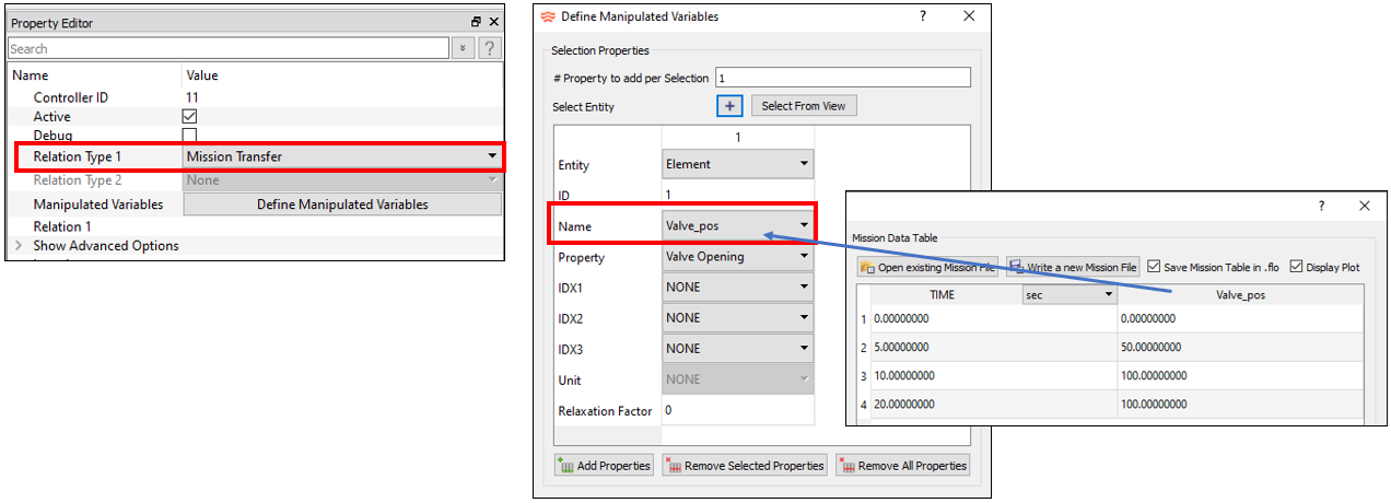
- GUI Screen Unit
- A Screen Unit (inch, mm, m, and so on) is now used to control model inputs that depend on item locations on the screen. These items include cavity surface points, elevation chamber height, and conductor resistor inputs. Most model items do not depend on the screen location, and the Screen Unit has no effect on these items. The Screen Unit MUST always match the units of the geometry file (IGES or STEP), including any geometry scale factor applied in the Flow Simulator GUI. For instance, if the geometry file is in millimeters and is scaled by a factor of 1/25.4 to make it inches, then the Screen Unit must be inches. The GUI automatically changes the Screen Unit to match the geometry file unit.
- If the cavity surface display is not in the expected location, the
screen unit may need to be changed. If the Screen Unit is changed, save
and reopen the model to display cavity surfaces in the new location.
Figure 5. GUI Screen Unit 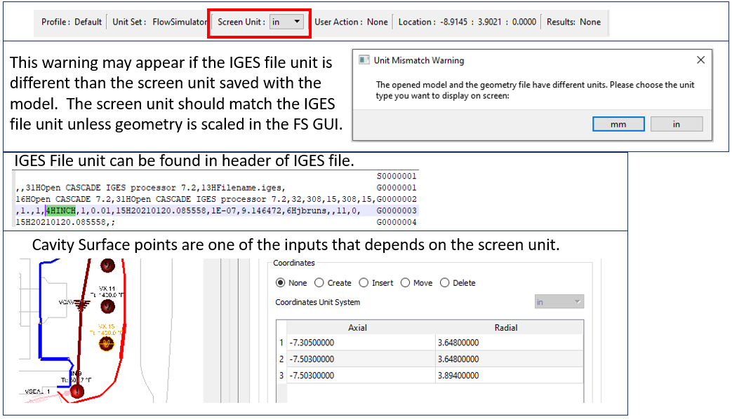
- Controller Python Comments for Arguments
- The GUI now automatically creates a new comment at the top of controller
Python scripts that contains the names of the gauge and manipulated
variables. This makes it easier to write a Python script since the
variable names are listed for you.
Figure 6. Python Comments 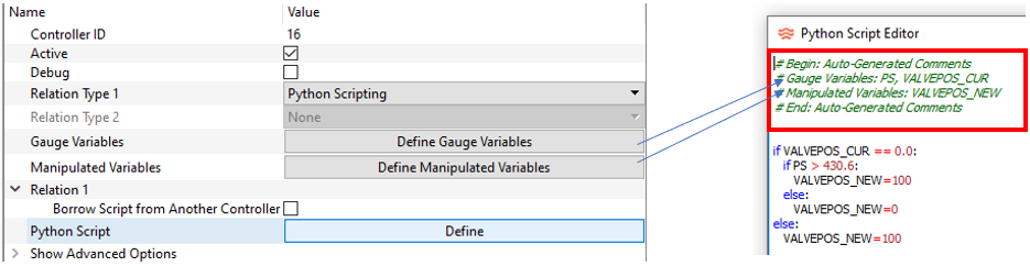
- Controller and FMU Multi-Edit
- Controller and FMU variable lists now have some multi-editing
capabilities. The Property and Unit row can be edited for multiple items
at once by selecting multiple column headers and then changing the
Property or Unit for one of the selected items. All the selected columns
are updated. The columns selected must have the same entity type (for
example, all chambers or elements).
Figure 7. Controller and FMU Multi-Edit 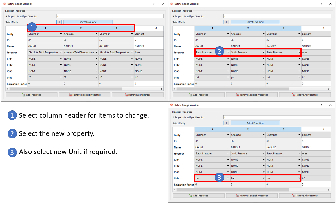
- Chemical Reaction Option for Incompressible Tube Element (BETA)
- The Incompressible Tube element now has a chemical reaction option that
allows species concentrations to change within the tube element. This
option only works with fluid properties from NASA CEA. Currently, the
only option is for custom reactions using the CHEM_REACTION subtype in
the customization manager.
Figure 8. Chemical Reaction in the Incompressible Tube 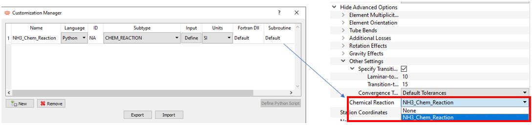
- Python Version Update to 3.11
- The Flow Simulator solver uses a dedicated set of Python files that are installed in the Flow Simulator installation folder. The Python version used in solvers controllers, UDE’s, and custom correlations has been updated to 3.11 This should not affect any existing models.
- Option to Turn Off CFL Criteria for Transient Time Step
- The transient solution time stepping used a CFL number criteria to
determine a minimum time step. The criteria is often too restrictive and
the transient can take smaller time steps than required. The CFL
criteria can now be turned off in the Transient Run Control Parameters
window.
Figure 9. CFL Time Step Criteria 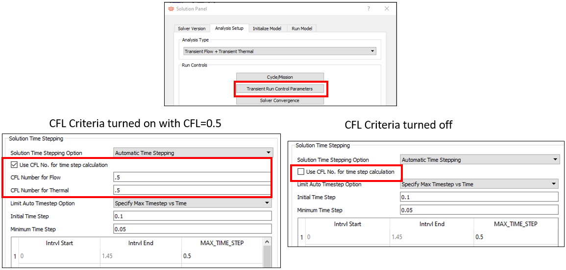
- Display Control for Controller Lines
- The lines from Controllers or FMUs to their associated items can be
toggled on and off. This can declutter the modeling window for models
with many gauge and manipulated variables.
Figure 10. Display Control for Controller Lines 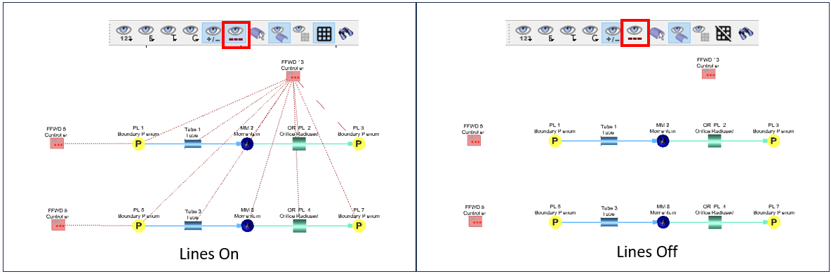
Known Issues
The following known issues will be addressed in a future release as we continuously
improve software performance:
- The FMU exported from Flow Simulator has not been tested with many different FMU importer programs. There may be issues when importing a Flow Simulator FMU into the other programs.
Resolved Issues
- Improved coupling of Advanced Tube and Incompressible Tube elements to thermal network convectors. The tube’s Q_CONV listed in the .res file now is more consistent with the attached convectors. This is most apparent for tubes with more than one wall side. The overall heat transfer Q is very close to the previous versions.
- Some Generic Heat Exchanger (GHX) thermal performance options were missing the area or GHX configuration.
- The “Initialize with Results” tool in the GUI now updates the thermal node temperatures. The previous version updated the flow chamber pressures and temperatures only.
- The Results Table now adjusts the number of decimal places based on the data values. Previous versions only used four decimal places, which is not sufficient for small values.
- The Results Table can now select results from tanks.
- The Results Table plots now have better minimum and maximum axis limits.
- Increased the limit for the number of teeth allowed in input tables for a Tooth-by-Tooth labyrinth seal from 40 to 100.
- The results display units now only consider the Unit Set units and not the units from the property editor. Previous versions would use multiple units for the results. For example, some pressure results displayed in MPa and some in bar.
- Built-in Convection correlations now transfer inputs when copying a convector.
- Problems with flow chamber and thermal node merging.
- Analysis Setup window “Default” button for different unit sets.
- Problems when renumbering accumulators.
- Allow Accumulators with virtual inertial chambers to have cavities.
- Fixed color display of the “Rotation Inlet Radius” and “Rotation Exit Radius” when plotting Element Inputs.
- “Heat Flow” can now be displayed in color for thermal network resistors.
- The CAD geometry files and background image files are now stored with absolute and relative paths in the model file (.flo).
- Controllers now have property options for vortex chambers and transition elements.
- The thermal node associated element is now updated when resistors, thermal nodes, and the associated tube element are all copied at the same time.
- Fixed a unit conversion problem with pasting data from Excel to a user-defined fluid property 2D table.
- Made a change to the standard tube element that allows it to converge for lower mach numbers (<.00012).