Altair Flow Simulator 2024 Release Notes
Highlights
- Flow Network Grouping in the GUI
- Turbulator Friction and Heat Transfer in Tube Elements
- Rotating Surfaces in Tube Elements
New Features
- Flow Network Grouping in the GUI
- Items in the flow network can now be grouped like thermal network
grouping introduced in the last release, 2023.1. The groups can be named
and colored. All entities displayed within the group can also be colored
with the group’s color. Collapsing the groups into blocks can help model
organization and visualization.
Figure 1. Flow Network Grouping in the GUI 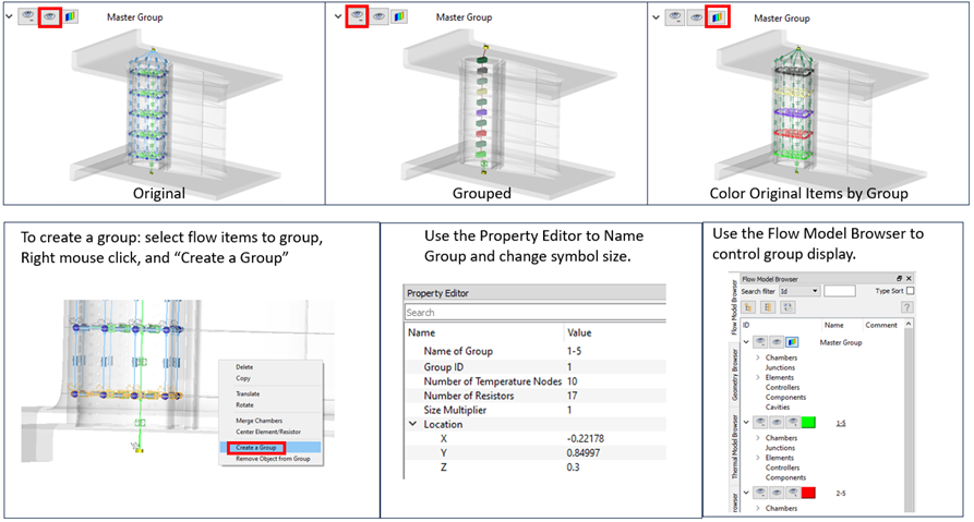
- Turbulator Friction and Heat Transfer in Tube Elements
- The advanced tube and incompressible tube elements now have turbulator
friction and heat transfer coefficient (HTC) options. The options for
the friction and HTC include:
- Webb Turbulator – Circular duct, square rib profile, 45 to 90 degree rib angle. Ref.: Webb, R. L., Eckert, E. R. G., and Goldstein, R. J. "Heat Transfer and Friction in Tubes with Repeated-Rib Roughness", Int. Journal of Heat and Mass Transfer, 14 (1971).
- TS Ravi Turbulator – Circular duct, multiple rib profile, 25 to 90 degree rib angle. Ref.: Ravigururajan, T.S., "General correlations for pressure drop and heat transfer for single-phase turbulent flows in ribbed tubes", Iowa State Univ, Thesis, 1986.
- Han 90 deg Turbulator – Rectangular duct with ribs on two opposing walls, square rib profile, 90 degree rib angle. Ref.: Han J.C., "Heat Transfer and Friction Characteristics in Rectangular Channels with Rib Turbulators", Journal of Heat Transfer, ASME (1988)
- Han Angled Turbulator – Rectangular duct with ribs on two opposing walls, square rib profile, 30 to 90 degree rib angle. Two references for low and high duct aspect ratio. Ref. for .25<W/H<1.0: Han, J. C., Ou, S., Park, J. S. and Lei, C. K. " Augmented Heat Transfer in Rectangular Channels of Narrow Aspect Ratios with Rib Turbulators" , International Journal of Heat Mass Transfer, 32, (1989) Ref. for 1.0<W/H<4.0: Han, J. C. and Park, J. S. "Developing Heat Transfer in Rectangular Channels with Rib Turbulators", International Journal of Heat Mass Transfer, 31, (1988).
Figure 2. Turbulator Friction and Heat Transfer in Tube Elements 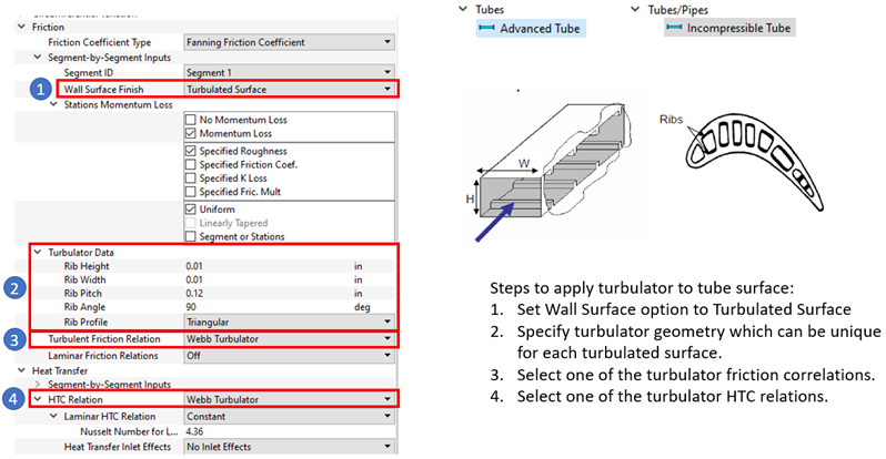
- Rotating Surfaces in Tube Elements
- The advanced tube and incompressible tube elements can now calculate the
fluid swirl and temperature change due to windage for an annulus or
coaxial shaft with a rotating surface. Previous versions would assume
the fluid swirl is the same as the tube rotation. If Rotating
Annulus or Rotating Coaxial Shaft
are selected, an angular momentum balance is calculated to get the
change of swirl and temperature. For instance, if fluid with a low swirl
(~0.1) enters a tube element with the inner surface of the annulus
rotating, the fluid swirl increases as it moves through the element. The
results file, *.res, has the details of the swirl
change. The friction factor and heat transfer coefficient correlations
use an effective velocity based on the relative tangential and axial
velocity.
Figure 3. Rotating Surfaces in Tube Elements 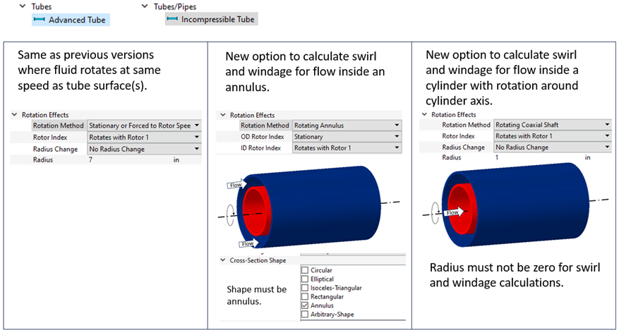
Enhancements
- Parallel Rotating Tube Heat Transfer Coefficient Correlation
- An additional HTC correlation is available to use with convection
resistors in the thermal network and with tube elements. The new
correlation is for a rotating tube that is parallel to and offset from
the axis of rotation.
Figure 4. Parallel Rotating Tube HTC Correlation 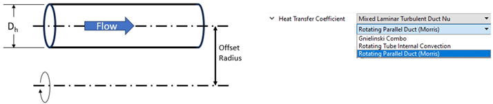
- New Generic Heat Exchanger Options
- The Generic Heat Exchanger (GHX) has one new pressure loss option and
three new heat transfer options. The “No Loss” pressure
drop option can be used when the fluid pressure drop is not important,
but solution speed is critical. The “No Loss” option
can significantly reduce solver solution time in models that have
multiple GHX components. The Fixed Fluid Exit Temperature options
determine the amount of heat transfer required between the hot and cold
stream to achieve a target exit temperature set for the hot or cold
stream. The Number of Transfer Units (NTU) can also be set to a constant
value.
Figure 5. New GHX Options 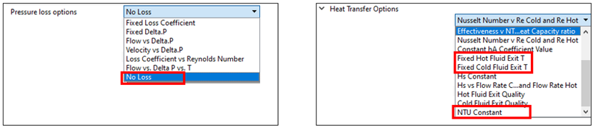
- Generic Heat Exchanger Matrix Modeling
- Generic Heat Exchanger components can be arranged in a matrix to capture
more details of the heat exchanger. For example, a vehicle radiator can
be modeled with a single GHX component using a single cold air inlet
temperature to calculate the overall heat exchange between the air and
coolant and a single air exit temperature. More detailed results can be
obtained by modeling the vehicle radiator with a matrix of heat
exchangers. Each heat exchanger in the matrix can have a unique air
inlet temperature and will have a unique air exit temperature. One of
the GHX components is declared the master and given inputs representing
the performance of the entire heat exchanger. All the other GHX
components in the matrix use the master GHX inputs. Thermal performance
discretization methods are NTU scaling or even heat exchange Q
distribution.
Figure 6. GHX Matrix Modeling 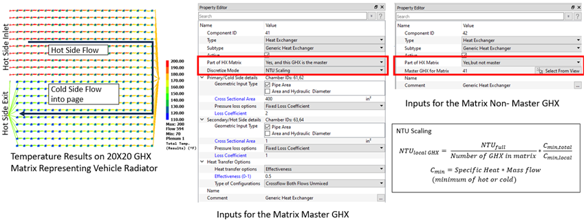
- User Defined Material Property Improvements
- The User Defined Material property window has the flexibility to use
more properties, so the ideal gas assumptions are not needed. This
allows for more accurate fluid properties for a “real” gas. For example,
the gas density and gas constant can be specified, and the
compressibility factor will be calculated.
Figure 7. User Defined Material Property Improvements 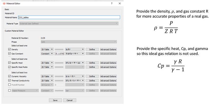
- Thermal Network Post-processing Improvements
- The GUI has new color contour plotting options for Heat Flow and Nodal
Heat on thermal networks. Thermal group post-processing includes
minimum, maximum, and average temperatures for thermal nodes in the
group. The Nodal Heat sum for the group is also available. Flow group
post-processing will not be available until the 2024.1 release.
Figure 8. Thermal Network Post-processing Improvements 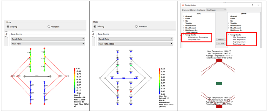
- Mission Parameter Unit Options
- The mission data table now has all the unit options available in Flow Simulator. This allows input of data like HTC in other unit sets.
-
Figure 9. Mission Parameter Unit Options 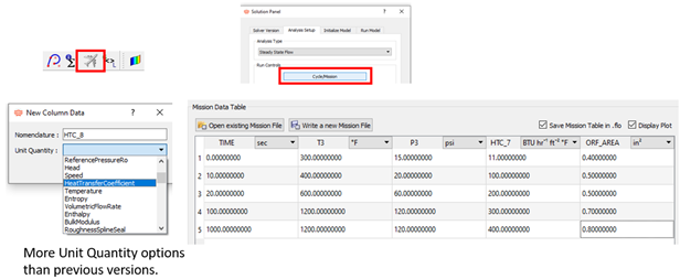
Known Issues
The following known issues will be addressed in a future release as we continuously
improve software performance:
- The FMU exported from Flow Simulator has not been tested with many different FMU importer programs. There may be issues when importing an Flow Simulator FMU into the other programs.
Resolved Issues
- Added a limit for the heat flow from the thermal network convector to a flow chamber. The heat flow is limited by the heat capacity of the fluid. The flow chamber is not allowed to rise above the wall temperature for heating or fall below the wall temperature for cooling.
- Changed the standard tube element that allows it to converge for lower Mach numbers (<.000001).
- The vortex element automatic flow flag option uses improved logic to try the various flow calculation options. If a model has worse convergence in the 2024 release, try changing the vortex flow flag to the automatic option.
- GUI problems with the multi-edit of controller and FMU variables.
- GUI problem with built-in heat transfer coefficient units’ conversion.
- GUI problems with rotating and scaling images.
- Accumulators now get proper fluid when clicking Apply in the Material Manager.