Altair Flow Simulator 2024.1 Release Notes
Highlights
- Changed element and resistor connections in the Property Editor.
- Junction automatic rotation.
- Blend free and forced convection heat transfer coefficient.
New Features
- Change Element and Resistor Connections in the Property Editor
- The upstream and downstream connections for flow elements and thermal resistors can now be modified in the Property Editor. This is especially helpful for changing many connections at one time using multi-edit. Change the connections for thermal resistors to a flow chamber by using the flow chamber number followed by a “C”.
- For example, connect a convector to flow chamber 5 by typing “5C” in the
Property Editor.
Figure 1. Change Connections in the Property Editor 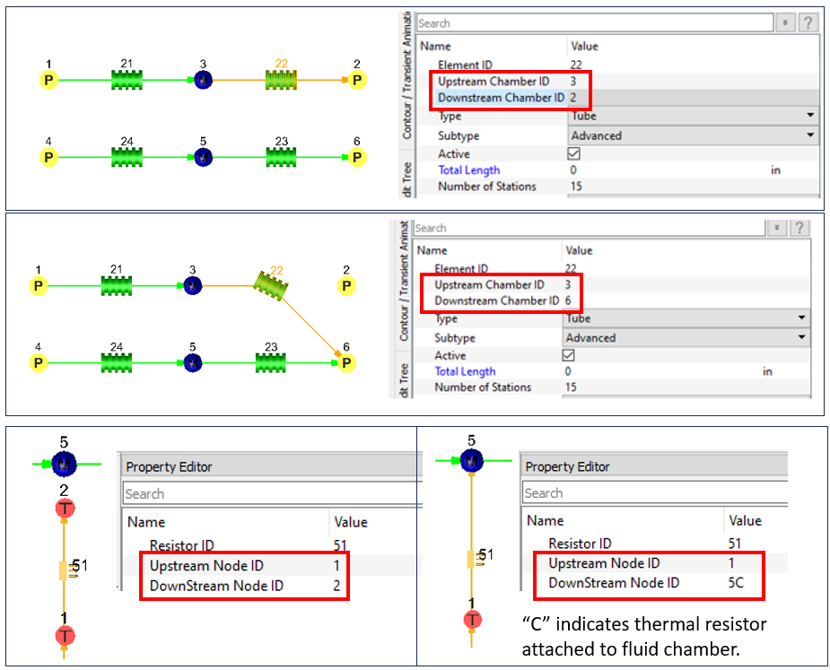
- New Electric Motor Component (Beta)
- The electric motor component has been added to the Element Library. This
component is used to describe various aspects of an electric motor thermal
model. It currently has inputs that can be used to run a transient duty
cycle analysis given a “loss” file generated by Altair's FluxMotor
program. This is considered a beta feature as more testing of various
modeling scenarios is needed.
Figure 2. New Electric Motor Component 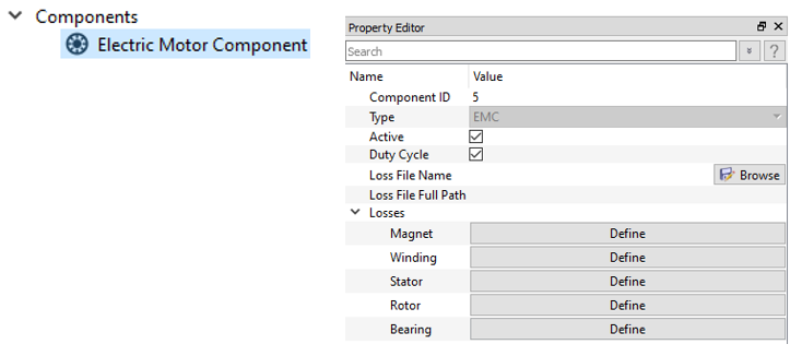
Enhancements
- Junction and Heat Exchanger Rotation Improvements
- The GUI now allows more control over junction and heat exchanger symbol
rotation. The junction also has an automatic alignment tool that finds the
best rotations for the junction relative to the attached elements. This
especially helps models using 3D space (not just 2D or X-Y plane). The
junction and heat exchanger angles can also be modified by typing the
rotation angles in the Property Editor.
Figure 3. Junction and Heat Exchanger Rotation Improvements 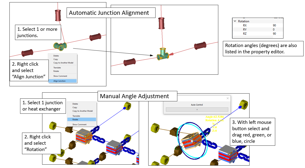
- Association Line Display Control
- Association line display can now be toggled on or off to help with model
visualization. There are four types of association lines that can be
toggled.
- Associated Lines: Lines from thermal nodes to tube element symbols (new in 2024.1).
- Controller Lines: Lines from the controller symbol to gauge and manipulated items (chambers, elements, thermal nodes, and resistors).
- Group Lines: Lines from the group block to any item or other group block that has a connection with any item in the group.
- Electric Motor Lines: Lines from the electric motor component symbol to the associated thermal nodes (new in 2024.1).
Figure 4. Association Line Display Control 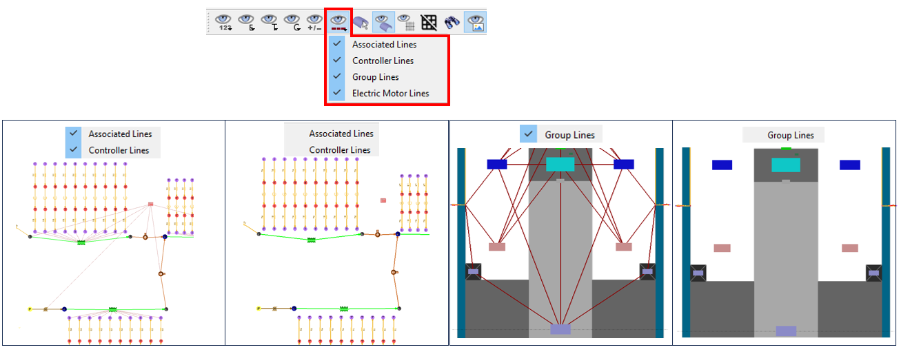
- Image Display Control
- The display of images can quickly be toggled on and off. This may help with
model visualization, especially when working in 3D.
Figure 5. Image Display Control 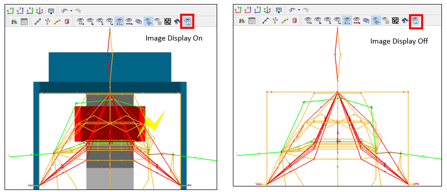
- Add Free and Forced Blending for the Heat Transfer Coefficient (HTC)
- All “built-in” forced convection correlations can now be blended with a free
convection (HTC). These are the HTCs that are used with thermal convectors.
This is useful if a model is expected to run with conditions that produce a
range of velocities in the system. At low velocities, a free convection HTC
may be higher than the forced convection HTC.
Figure 6. Free and Forced HTC Blending 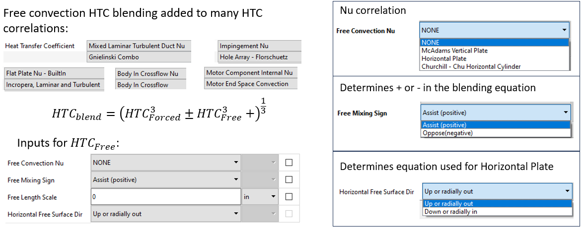
- Heat Transfer Coefficient Improvements
- Improvements to the heat transfer coefficients used by thermal convectors
include:
- New flat plate correlation that includes equations for laminar Re, turbulent Re, local or average HTC, and free HTC blending.
- New correlation for a turbulated tube. It uses the same correlation for a turbulated surface that was added to the advanced and incompressible tube in the 2024 release.
- Added an option to include swirl in the velocity calculation for the Gnielinski Combo duct flow correlation.
- Added an option to include the total velocity or velocity components (axial, radial, tangential) for a body in crossflow correlation.
- Added Automatic Flow Equation Option
- The valve element and the expansion/contraction elements now have an
“Automatic” flow equation type. This allows the element to automatically use
the compressible equations if a gas is entering the element and
incompressible equations if a liquid is entering the element.
Figure 7. Automatic Flow Equation Option 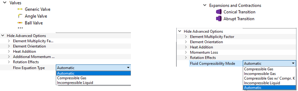
- Add New Unit Set Checks during Model Open
- The GUI now checks if the unit set saved in a .flo file already exists in your unit set library (saved in the AppData\Local\Altair\FlowSimulator folder). If a unit set with the same name is found, the GUI checks each Unit Quantity. If there are discrepancies between a Unit Quantity, you are prompted to make a choice.
- Copy Items from One GUI Instance to Another
- The GUI can now copy flow chambers and elements from one GUI instance to
another. Thermal items can’t be copied using this method. The element and
chamber numbers do not remain the same when copied. Do not copy an element
without including its upstream and downstream chambers in the selection.
Figure 8. Copy Items from One GUI Instance to Another 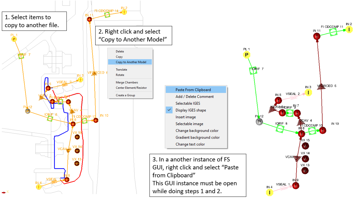
Known Issues
The following known issues will be addressed in a future release as we continuously improve performance of the software:
- Some very large models or models using a small screen unit (like millimeters) can have text that is too small to read. The maximum size of 80 may be too small. Using a different screen unit may allow for larger text.
Resolved Issues
- Problem with elevation chamber units.
- Disappearing resistor lines during certain operations, such as reversing the direction.
- Missing convector surface area input for convectors attached to vortex flow chambers.
- Missing HTC correlation options for a convector attached to vortex flow chambers.
- Thermal resistance units problem while post-processing with SI units. Also added Thermal resistance to the Display Options list.
- GUI crash when placing a junction directly on a chamber.
- Problems with pasting data into various tables in the GUI. The GUI will now add enough rows to accept all data pasted.
- GUI crash when comparing models using the Model Compare tool.
- Problem with automatic bend element creation from geometry.
- Updates to improve speed and accuracy of fluid property retrieval in the solver.
- Improved thermal solver damping to help thermal model convergence for some models.
- Solver problem if the junction does not converge during the first iteration.