Altair Flow Simulator 2022.3 Release Notes
Highlights
- Smart element creation.
- Cavity surface creation using CAD curves.
- Merge chambers or thermal nodes.
- Processing controls for controllers.
New Features
- Smart Element Creation
- With this new feature, you can create elements faster by automatically connecting an element to the closest chamber or grid location. Press the “s” key while dragging an element from the element library to the screen to enable smart creation. A red circle indicates the upstream chamber, and the blue circle indicates the downstream chamber. Release the mouse button to automatically create the element and attach it to the chambers.
-
Figure 1. Smart Element Creation 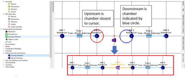
- Cavity Surface Creation Using CAD Curves
- You can select cavity surface points directly on CAD curves. Previous versions only used the cursor position on the screen for point creation. To create single points, click on the curve or create multiple points with one click.
-
Figure 2. Cavity Surface Creation 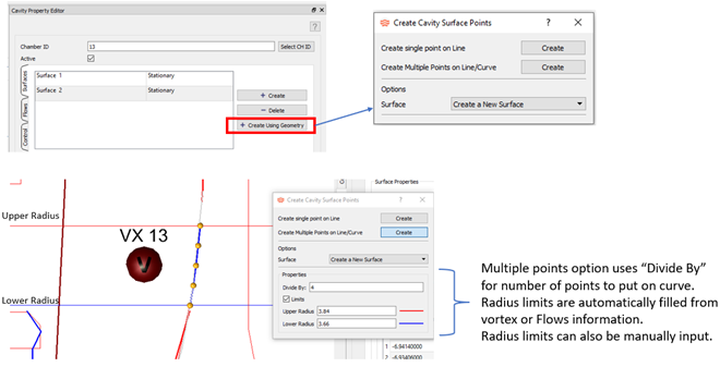
- Merge Fluid Chambers or Thermal Nodes
- You can automatically merge chambers or thermal nodes that lie close to one another. This is useful if duplicate chambers exist after copying a group of elements. It can also be used if automatic element creation using CAD leaves two disconnected elements that should be connected. Use Discard or Undo if there are problems with the merge.
-
Figure 3. Merge Chambers or Nodes 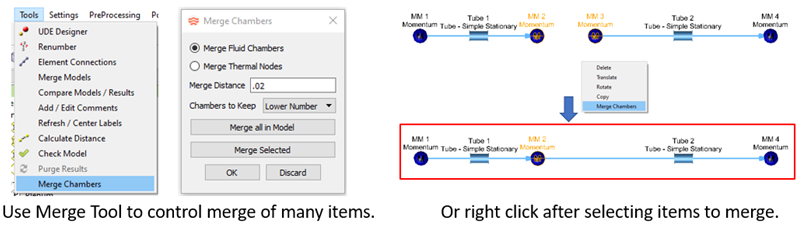
- Add Processing Controls to Controllers
- The following three types of processing controls have been added to
controllers to improve performance and convergence:
- Iteration Control - Run the controller at specified iterations. Use this instead of adding iteration checks to Python.
- Flow Convergence Control – Run the controller when flow convergence has reached a multiple of the convergence target. Ten times is default.
- Gauge Change Control – Run the controller when gauge variables have changed more than a given percentage since the last controller run. If multiple controls are active, the controller is processed if any of the controls are “true”. If the controller is not run, then manipulated variables remain at the same value as the previous controller run.
-
Figure 4. Controller Processing Controls 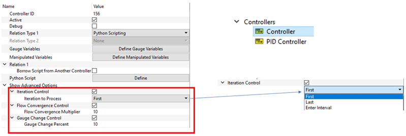
- New Fluid Liquid/Gas Separator Element
- A new element separates liquid or gas from a two-phase stream at a chamber. You are required to enter the mass fraction of the liquid or gas to remove. You can use a controller to calculate the separation fraction if needed.
-
Figure 5. Fluid Liquid/Gas Separator 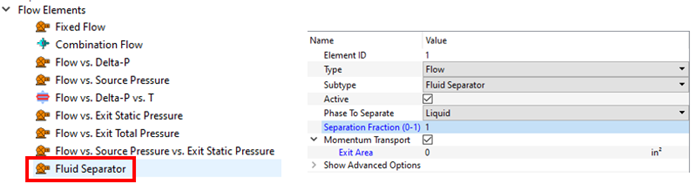
Enhancements
- Labyrinth Seal Tooth Dependent Inputs
- You can input several inputs of the Tooth-by-Tooth labyrinth seal for each tooth. The inputs include tooth geometry such as Pitch, Width, Height, Angle, and Radius from the engine centerline. The Tooth-by-Tooth and Vermes seal have a swirl carryover that can be entered for each tooth. The loss methods for the first tooth of the Tooth-by-Tooth seal have been changed to ignore kinetic energy carryover and stepped effects. This change improves the match to validation data.
-
Figure 6. Labseal Tooth Dependent Inputs 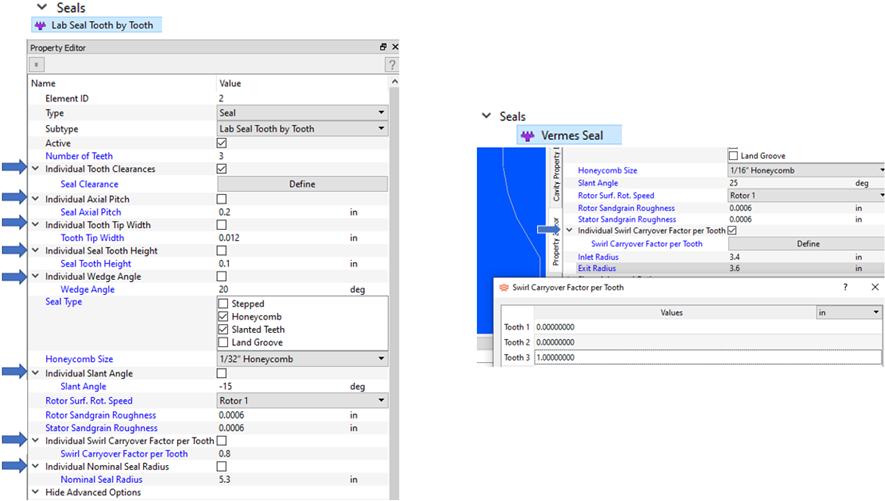
- Selection Filters
- A selection filter is available in the Property Editor to specify which items remain selected for editing. You can select multiple items, sweeping across the screen while clicking the left-mouse button. For example, use the filter to only keep chambers.
-
Figure 7. Selection Filter 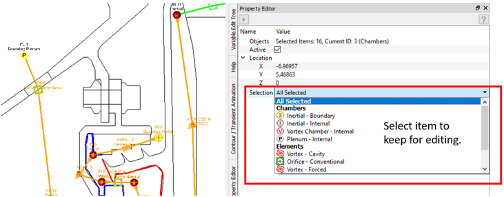
- Thermal Resistance Inputs for Conductors and Convectors
- Thermal resistors take a thermal resistance input in place of geometric and material properties. New input makes it convenient when you need to enter a thermal resistance.
-
Figure 8. Resistance Input for Conductor and Convector 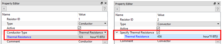
- Fixed Flow Element Exit Radius
- The fixed flow element has an exit radius input. Previous versions just had a single radius. Use the exit radius for models using fixed flows instead of typical elements (like vortex and orifice) in simplified cavity analysis. If the exit radius is 0, it is assumed to be the same as the inlet radius.
-
Figure 9. Fixed Flow Element Exit Radius 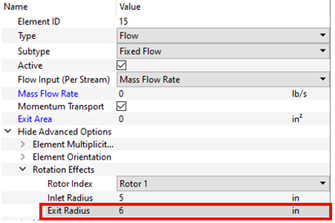
- Fixed Flow Element Velocity Input
- The fixed flow element has an option to enter the velocity of the flow. Previous versions had options for mass and volumetric flow rates. The velocity option requires a flow area to be entered, too.
-
Figure 10. Fixed Flow Element Velocity Input 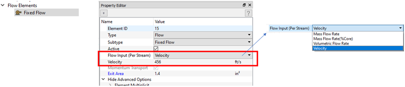
- Aluminum and Copper Solid Properties
- Material properties for aluminum and copper are now included in Flow Simulator.
-
Figure 11. Aluminum and Copper 
- Solid Properties Written to the *.prop File
- Solid properties are located at the bottom of the *.prop file. The solid properties are only written for models that include thermal networks.
- Control of Coolprop Mixtures
- Coolprop has difficulty with some fluid mixture combinations. A new option mixes Coolprop species using Flow Simulator mixture rules instead of having Coolprop mix internally. Only use this option if Coolprop fails during its own mixing. The properties of the individual species are retrieved from Coolprop. Flow Simulator uses these properties to calculate the mixture properties.
-
Figure 12. Coolprop Mixture Control 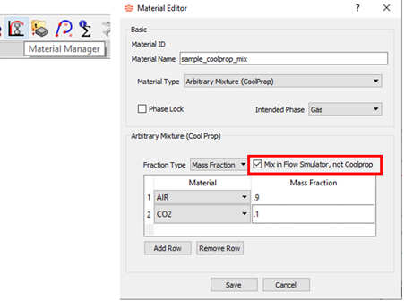
- Screen Output Automatically Reduced for Long Runs
- Screen output is automatically reduced after the solver iteration count reaches certain thresholds (5,000 and 10,000) during a long run. This typically happens for transient analysis. This change is intended to improve performance. You can still find all convergence information in the convhist_fi.out file.
- Improve Reynolds Number Correction
- Several elements (orifice plate, transition, valve) use a Reynolds number correction for loss factor (k). Many empirical k’s are based on a turbulent Re. If an element has a laminar Re, the turbulent k is corrected. The correction factor can come from tables or an equation. The existing tables were modified to improve performance of the linear interpolation. The equation option was added to the junction and bend.
-
Figure 13. Re Correction Improved 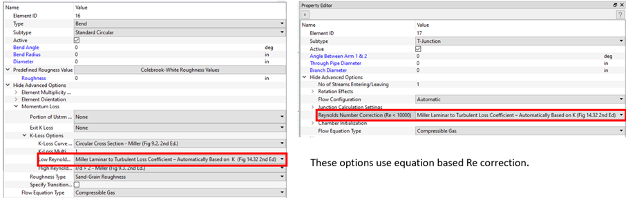
- Move Existing Chamber to a Vertex
- Follow the steps below to move an existing chamber (or thermal node) to a vertex.
-
Figure 14. Move Chamber to Vertex 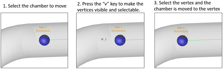
- Batch Mode - New Option to Import Custom Correlations
- Use the user interface batch mode to load a file containing custom correlations. This option is useful when building or updating a model using batch.
-
Figure 15. Custom Correlation Import in Batch Mode 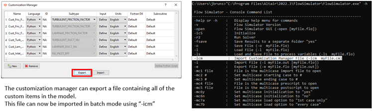
- Automatic Element Creation Improvements
- The user interface process for automatic element creation is more robust and faster. The Scan All option creates elements on all cylindrical surfaces in the model that fall within a user-supplied radius range.
-
Figure 16. Auto Element Creation 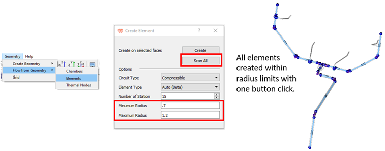
Known Issues
The following known issues will be addressed in a future release as we continuously
improve software performance:
- The new controller interface does not work with controllers that have two relations (for example, 1D table and Python script in the same controller).
Resolved Issues
- Fixed solver to release Altair license immediately when you stop the solver before the end of a run.
- No longer allow the Robust solver to be used with the Enthalpy energy option. Robust solver does not work correctly so the program automatically switches to the standard solver.
- The vortex element was not calculating the correct relative temperature. This only affected a vortex element attached to plenum or momentum chambers in the relative frame. Most vortex elements are attached to inertial chambers so they are not affected by this.
- Temperature change limits added to labseal elements to improve robustness.
- Correct labseal pocket heat transfer to use relative instead of absolute total temperature on a rotating surface.
- Fixed user interface problems when trying to create elements from CAD for certain types of surfaces.
- Made the solver version obvious from the Run window so it's clear if a user-specified solver is selected.
- Fixed several problems with importing and exporting files from the user interface.
- Fixed missing Rotation Effects input in the user interface for transition elements.
- Fixed missing unit for fixed flow element flow rate in the multi-case creator.
- Change to correct HTC Relation for Simple Stationary and Simple Rotating compressible tubes.
- Fixed solver bug for Arbitrary Mixture (Coolprop) when Fraction Type = Mole Fraction.
- Change to INCO 625 and PTFE thermal conductivity to improve match to references.
- Valve position has a unit in the interface (percent open and degrees). Where 0%=0 degrees and 100%=90 degrees. This unit is recognized by the Variable Editor.
- Fixed issues with the solver’s compressible initializer.
- Fixed issue with the pressure units of “bar” used in controller or FS_coupling.dat.
- Fixed issue when multiples of the same PROPERTY name are used in the file FS_coupling.dat for HyperStudy DOE’s.