Altair Flow Simulator 2022 Release Notes
Highlights
- In the GUI, you can plot model inputs using color contours.
- Center element symbol.
- Improved creation of flow elements using CAD geometry.
New Features
- Plot Model Inputs Using Color Contours
- Use color contour plots to visualize common model inputs, such as
restriction diameter or length. Use this feature to quickly check model inputs.
Figure 1. Tube Length Plot 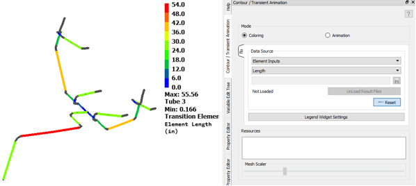
- Center Element Symbol
- The flow element symbol can be automatically centered between its
chambers. This can be used during element creation or can be used on
existing elements. This also works for thermal resistors.
Figure 2. Centering Symbols 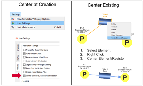
- Energy Equations with Enthalpy (BETA Release)
- A new option has been added to use enthalpy instead of temperature for
energy conservation calculations. This is only valid when Coolprop is
used for fluid properties. This option also includes the Joule-Thomson
effect on temperature. Phase change is not yet included in Flow Simulator.
Figure 3. Energy Equation Options 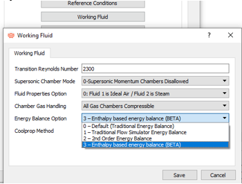
- Cv Flow Coefficient Element
- The flow coefficient typically called Cv (or Kv) can be used on a
generic element. Cv has the units of GPM/sqrt(psi) ( or
m^3/hour/sqrt(bar) ) and is typically used to characterize the flow rate
in a valve. The simple Cv element can be used instead of a valve when
the flow restriction flow rate has a constant Cv. The Cv element can be
used with compressible gas or incompressible liquids. The equations used
in this element come from ISA-75.01.01-2007.
Figure 4. 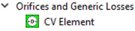
Enhancements
- Compressibility Factor Used for Coolprop Fluids
- The gas density calculations in Flow Simulator now include the
compressibility factor (z) for increased accuracy. Any equation that
used the ideal gas equation now includes z. This only works when
Coolprop is used for fluid properties. z=1 for all other fluid property sources.
- Added New Fluid Property Options
- Added the “incompressible” liquids from Coolprop. This includes typical automotive coolants.
- CdComp Reverse Flow Options
- Option added to calculate the Cd differently if flow reverses through the element. Options include using a different corner treatment or specifying a Cd for reversed flow.
- CdComp Incidence Angle Effect
- Modified Cdcomp discharge coefficient (Cd) for high incidence angle and hole that is at an angle to the part surface. High negative incidence angle (angle < -15o) and positive incidence angle (30o) are affected. Most difference occurs if the hole is angled > 30o to the part surface. Change produces smoother results for a wider range of incidence angles. This did not change the Cd for holes that are perpendicular to the part surface.
- Thermal Node Includes Rotation
- The thermal node includes a surface rotation input. This is useful for
convectors attached to inertial or vortex chambers that are being used
for cavities in turbomachinery applications. Flow Simulator calculates a
relative total temperature to use for the convection heat transfer to a
rotating surface.
Figure 5. Surface Rotation for Thermal Node 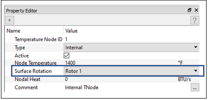
- Improved Fluid Element Creation from CAD
- The Geometry drop-down menu has all GUI functions
that enable flow element creation from CAD geometry. This is useful when
a CAD model of a piping system is available. Chambers and elements can
be created using the CAD.
Figure 6. 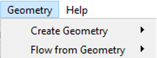
- Vertices can be created on geometry. A chamber can be created at the
same time as the vertex, or chambers can be placed on a vertex later.
Chambers can also be created using a table of X,Y,Z locations.
Figure 7. Vertex Creation 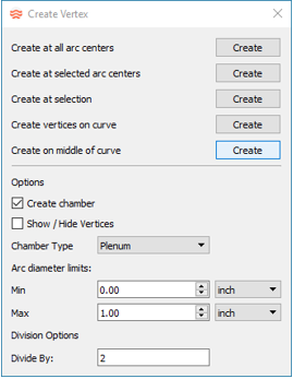
Figure 8. Chamber Creation 
- Some geometry surface types allow you to create an element directly from
the geometry. Use the Create Element panel to
select a surface for element creation.
Figure 9. Element Creation 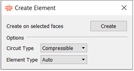
- Custom Correlation Option for Heat Addition
- You can use the custom heat addition for the orifice element, tube elements, and the heat flow resistor in thermal networks.
- Custom Correlation Option for Cavity HTC
- You can use the custom cavity Heat Transfer Coefficient (HTC) on convectors when a fluid chamber is convecting to a rotating or stationary surface.
- Custom Correlation Output
- Information about custom correlations is now written to the *.res file. You can also fill text variables to write to the .res file. There is a new subroutine argument that must be added to all custom correlations in FORTRAN. The new argument is the subroutine name: CUST_FILL_OUTPUT_STRING. See the examples in <FlowSimulator_install_folder>\Resources\Customize\fs_custom_lib.f.
- Flow vs. Delta P vs. Delta T Added to Heat Exchanger
- Added another pressure loss option to the generic heat exchanger.
- Jacketed Pipe Improvements
- The thermal nodes created by the jacketed pipe have a volume input. The
jacketed pipe can include another element to model heat exchange between
two elements. An existing jacketed pipe can be edited by selecting it
from the Domain Browser.
Figure 10. Jacketed Pipe Improvements 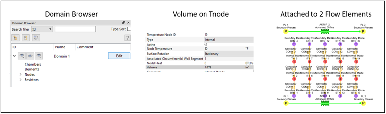
- Standard Volumetric Flow Rate Added to Flow Elements
- Some of the Flow Element types have an option to specify a Standard
Volumetric Flow Rate. This option also requires you to enter the
standard temperature and pressure corresponding to the Standard
Volumetric Flow Rate input.
Figure 11. Standard Volumetric Flowrate 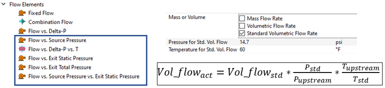
- Added Gauge and Manipulate Variables in Controllers
- Some of the new variables available for controllers include:
- Reverse Element Direction
- Double-click with the left mouse button to quickly reverse the direction of an element. The double-click should be done on the element symbol.
- Geometry Edge Radius and Length
- You can select a geometry edge to display radius, diameter, edge length,
and area for a circle. Click the icon to enter the edge selection mode.
Select the edges to examine. Click the icon again to exit edge selection mode.
Figure 12. Edge Geometry Information 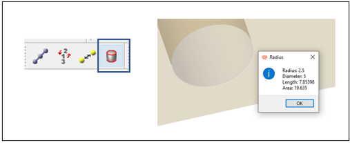
Known Issues
The following known issues will be addressed in a future release as we continuously
improve performance of the software:
- The Create Element from Geometry option may not recognize some surface types and may fail to create an element.
Resolved Issues
- Units conversion (SI to English) for flow derivatives (dw/dP) returned from UDE code.
- Added precision to units’ conversion to minimize unexpected small differences in model inputs displayed in the GUI.
- Writing a Reynolds Number that uses the effective hydraulic diameter for tubes and the advanced orifice. The effective hydraulic diameter is different than (4 x area)/perimeter for non-circular shapes. The effective hydraulic diameter is used to calculate a more accurate friction factor and HTC for non-circular shapes.
- The Brush Seal element had a non-physical change in the calculated flow rate when the Reynolds number changed from laminar to turbulent.