Altair Flow Simulator 2025.1 Release Notes
Enhancements
- GUI Text Magnifier
- The GUI text magnification was introduced in version 2025 to improve
text visibility for models that are very big or small. In this release,
pressing the “m” key displays text for all items in the modeling window.
There is also a new text size option of 0, which is useful for very
small models where the text size of 0.5 was too big.
Figure 1. 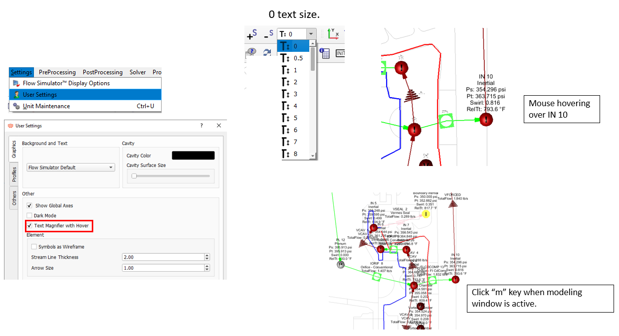
- CV Element Changes
- The CV element now uses the static pressure in the upstream chamber for
the flow rate equation. This corrects previous versions that used the
element angle dependent pressure, PTS, which could have been a total
pressure. This can cause results changes if the total and static
pressure are significantly different in the chamber upstream of the CV
element. The CV element will also calculate a flow scale factor for
laminar flow. The laminar calculations require a pressure recovery
factor, FL, for compressible as well as incompressible fluids. Also, the
valve style modifier, FD, is a new input for compressible and
incompressible. The equations used in this element come from
ISA-75.01.01-2007.
Figure 2. 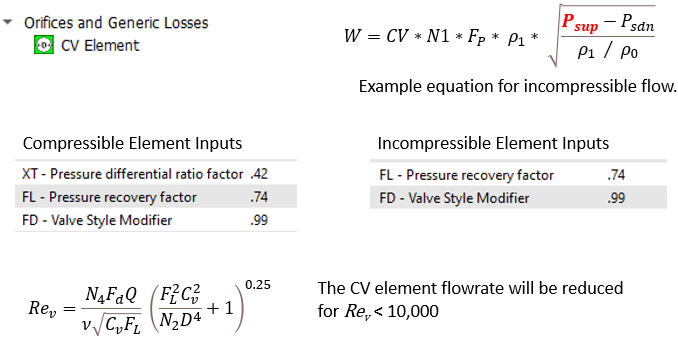
- Cavitation Check for Liquid in Valve Element
- The incompressible valve element now checks for cavitation of liquid
fluids. For a liquid, choking can occur when the static pressure in the
valve is low enough for cavitation (vaporization) to occur. The valve
element uses the same check as found in the CV element (and
ISA-75.01.01-2007). This new check requires the input of a compressible
gas correction factor for the valve element. This factor is converted to
the “CF” factor, which is equivalent to the “FL” pressure recovery
factor in the ISA document. If cavitation is detected, the valve element
uses a downstream pressure equal to the vapor pressure, PV, to calculate
the flow rate.
Figure 3. 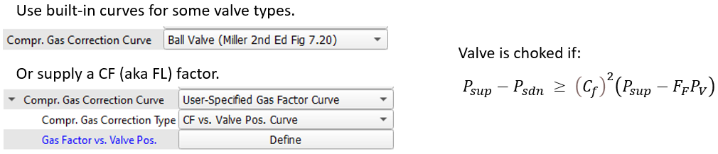
- Model Copy/Paste Includes Cavities
- Model items can be copied from a model in one GUI instance to a model in
another GUI instance. Cavities will now be copied when selecting the
inertial or vortex chamber that has an associated cavity.Note: After step 2, the text representing the copied items can be pasted into a text editor using Ctrl+V. This text is similar to that when using the option, except it only contains information for the selected items.
Figure 4. 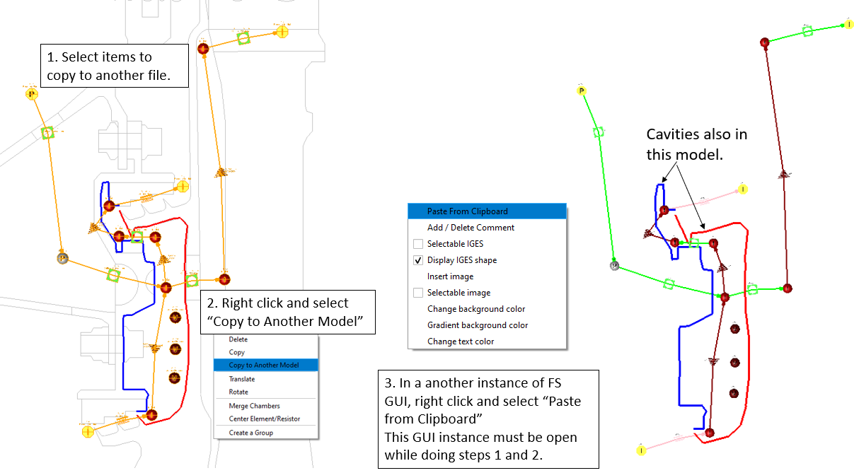
- Sub-cool and Superheat Options for Elements and Generic Heat Exchangers (GHX)
- Several elements and the GHX now have heating options for sub-cooled
liquid and superheated gases. This is useful for models with phase
change where temperature targets are a known delta above or below the
saturation temperature. These new options are available for several
elements (for example, orifice and fixed flow) and the GHX. Note that
models with phase change must use a fluid from Coolprop and the
Enthalpy-based energy equation.
Figure 5. 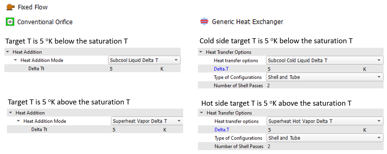
- Improved GHX Phase Change Capability
- The GHX can now accurately account for phase change for most thermal
performance options and matrix configurations. The NTU method is not
suitable when both the hot and cold sides have phase change, since the
NTU method requires a minimum heat capacity. The side (hot or cold) with
the minimum heat capacity is assumed to be the side without phase
change.
Figure 6. 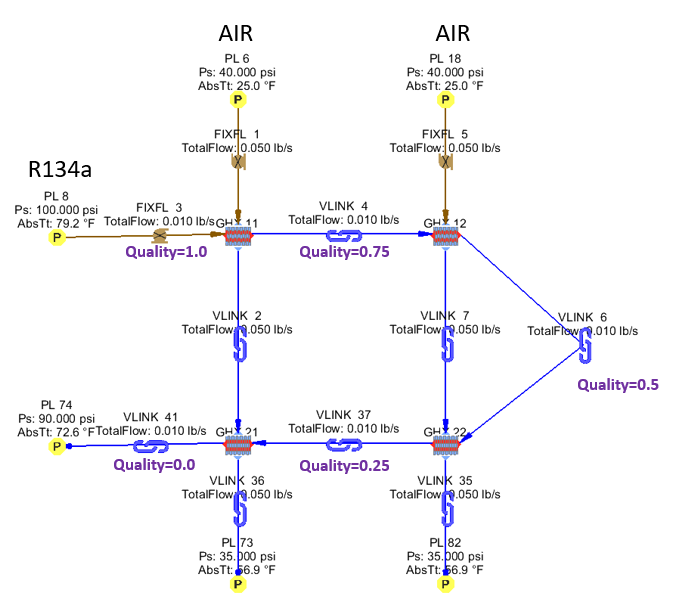
- Mission Transfer Controllers for Thermal Nodes and Resistors
- The controller using the relation Mission Transfer can now select thermal nodes and resistors. The Mission Transfer controller is the easiest way to transfer time-dependent information directly from the mission to a modeling item (for example, temperature versus time to a thermal node). In previous GUI versions, mission transfer only worked for flow chambers and elements.
- New Groove Method for Lab Seal Elements
- A minimum clearance method has been added to the Vermes and
Tooth-by-Tooth Lab Seal elements. This method calculates the minimum
distance from the tooth to the honeycomb groove. This distance is used
as the clearance for the seal flow rate calculations.
Figure 7. 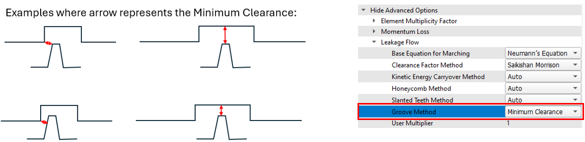
- Solver API Improvements for Multiple FS Model Coupling
- The solver API can now handle the running and coupling of multiple Flow
Simulator models, even if one of the models does not converge during an
intermediate run. This coupling has been demonstrated using a gas
turbine blade supply model and a blade model.
Figure 8. 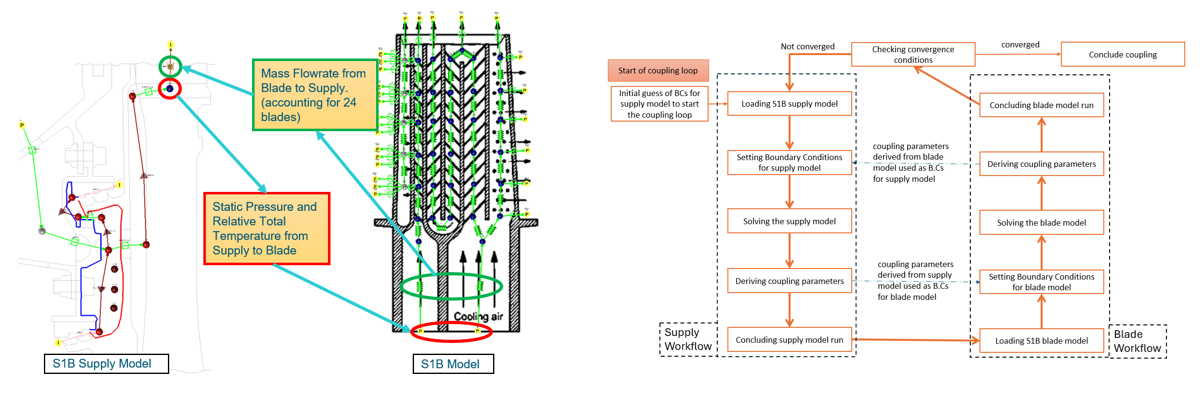
- GUI Copies the FS_coupling.dat to a Separate Folder
- The GUI can launch the solver in a separate folder. This helps organize
runs, especially when performing multi-case analysis. If the model
folder contains an FS_coupling.dat file, it is
automatically copied to the separate folder before the solver is
started. This ensures that the solver gets the inputs from the “TO_FS”
lines and records the run output in the “FROM_FS” lines in the
FS_coupling.dat file.
Figure 9. 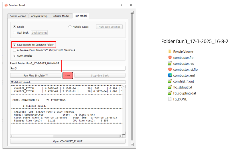
Deprecated Features
The following features and options have been deprecated in Flow Simulator 2025.1:
- The option has been removed, since it is not needed with grouping done with the Flow and Thermal browsers.
Resolved Issues
- You may have experienced problems moving an item using the Ctrl key. The user interface would sometimes enter rotation mode since Ctrl is also used for rotating the view. The GUI now accepts the Alt key to move items. The Ctrl key still works for moving, but Ctrl will be deprecated in a future release.
- GUI issue for controllers using CV elements or Cdcomp elements where the Add New Property for gauge and manipulated variables was not loading correctly.
- The GUI does not allow elements to be connected to vortex chambers when using the Property Editor to change element connections.
- The following GUI issues have been fixed:
- Associated Line visibility control.
- Long results file names and folders caused the GUI window to be trimmed on the right edge.
- Invalid error messages when elements use the Automatic Area method.
- Text magnifier issue, which caused a GUI crash.
- Controllers using one of the advanced options not reading correctly.
- Opening a model with an electric motor component that has long path name to the loss file.
- Creating an unreadable model after copying GHX.
- Mission is missing a PRINT_TIME_STEP column.
- Reading a results file (*.res) when the orifice plate element has a nonzero exit K loss.
- Mission has values greater than 1000 in neighboring rows.
- Radiators using the Radiation between two surfaces option. The view factor for Right-to-Left was displayed as a negative value.
- Color contour legend is not consistent with selected property.
- The User Defined Element (UDE) designer is opened while an element is selected.
- GUI now plots color contours for thermal nodes for the Relative Total Temperature as well as the Absolute Total Temperature.
- GUI now uses better logic to display enough significant digits in the Results Table when an *.rt file is used.
- Solver issue with choke and surge volume flow rates for the axial compressor and turbine. Choke and surge warnings are now written to results files for all fans, compressors, and turbines.
- Increased the number of mission parameters allowed from about 30 to about 200. This was a solver limit. The GUI already allowed more than 200 parameters.
- The GUI can now change any chamber type to a Generic Fixed Volume (GFV). The previous version only changed momentum chambers to GFV.
- Issue with the Flow Simulator and HyperStudy data transfer. Output responses will now transfer successfully.
Known Issues
The following known issues will be addressed in a future release:
- Visibility of some items in dark mode will be improved in a future release.
- There are some problems when using copy and paste between models with thermal nodes and resistors that belong to a group.
- The new post-processing for “Group Heat Flow” may not sum the heat flows correctly for complex groupings.