Blunt Body
- Type
- Body in Crossflow Nu
- Subtype
- Body in Crossflow
| Index | UI Name (.flo label) | Description |
|---|---|---|
| 1 | Shape (SHAPE_ID) |
Shape of the body in the cross flow. The shapes available in the correlation are mentioned in the Formulation section. |
| 2 | Velocity Input Type (VEL_ID) |
Methods available for the user for velocity input:
Further discussions are in the Formulation section. |
| 3 | Velocity (FLOW_VEL) |
This is activated only if User Input is selected as the “Velocity Input Type”. It takes the user input velocity. |
| 4 | Characteristic Length (CHAR_LEN) |
The characteristic length/diameter of the fluid flow. “d” in the Formulation section. |
| 5 | Outer Radius (OUTER_R) |
The stator outer radius. This is activated only if
RPM Based is selected as the
“Velocity Input Type”. If “Auto”, then Outer Radius = 0.5 * Characteristic Length. |
| 6 | Tip Speed Ratio (TIP_SPD_RATIO) |
The frame tip speed ratio, user-defined. |
| 7 | HTC Multiplier (HTC_MULT) |
A constant multiplier to scale the value of heat transfer coefficient obtained from the correlation. |
Formulation
This correlation uses a Nusselt number that can be found in references 1, 2, and 3. A linear interpolation is used if the Re is in the transitional regime.
Reynolds Number:
With:
: The external fluid velocity.
: The characteristic length/diameter of the fluid flow.
: The external fluid flow viscosity, at the film temperature.
: The external fluid density.
| Velocity Input Type | Comments | Formulation |
|---|---|---|
| Chamber | This is the default method. This takes the velocity that is calculated in the fluid chamber attached to the convector. | |
| User Input | In this method, you can directly input the velocity. | |
| RPM Based | This method requires the outer radius and tip speed ratio for calculation of the velocity. It is further explored in Formulation section. |
With: : The angular speed of the rotor. : The outer radius. : The user-defined tip speed ratio. |
Nusselt’s number:
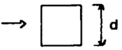
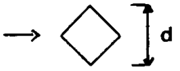
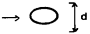
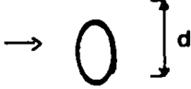
| Shape Name in GUI | Shape Demonstration | Re | C | m |
|---|---|---|---|---|
| Square |
|
2.5*103 – 8*103 | 0.180 | 0.699 |
| 5*103 - 105 | 0.102 | 0.675 | ||
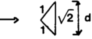
| Rhombus |
|
5*103 - 105 | 0.25 | 0.588 |
| Horizontal Ellipse |
|
2.5*103 – 1.5*104 | 0.25 | 0.612 |
| Vertical Ellipse |
|
3*103 – 1.5*104 | 0.096 | 0.804 |
| Horizontal Hexagon |
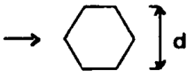
|
5*103 - 105 | 0.156 | 0.638 |
| Vertical Hexagon |
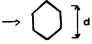
|
5*103 – 1.95*104 | 0.162 | 0.638 |
| 1.95*104 - 105 | 0.0395 | 0.782 | ||
| Thick Vertical Plate |
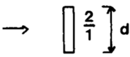
|
3*103 – 2*104 | 0.264 | 0.66 |
| Thin Vertical Plate |
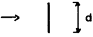
|
4*103 – 1.5*104 | 0.232 | 0.731 |
| Horizontal Triangle |
|
3*103 – 2*104 | 0.246 | 0.61 |
| Cylinder |
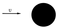
|
This follows Churchill-Bernstein convection correlation. For more information, see Heat Transfer Coefficients (HTC) Correlations and view the section Churchill-Bernstein (Cylinder in Cross Flow). | ||
| Index | .flo label | Description |
|---|---|---|
| 1 | TNET | Thermal network ID which has the convector where this correlation is used. |
| 2 | CONV_ID | Convector ID which is using this correlation. |
| 3 | SHAPE | Shape of the body in cross flow. |
| 4 | CHAR_LEN | Characteristic length. |
| 5 | OUTER_R | Only appears if RPM Based velocity type is selected. Displays the value of outer radius used in the calculations. |
| 6 | TIP_SPD_RATIO | Only appears if RPM Based velocity type is selected. Displays the value of tip speed ratio used in the calculations. |
| 7 | VELOCITY | The velocity used in the calculations. |
| 8 | PR | Prandtl number. |
| 9 | RE | Reynolds number. |
| 10 | NU | Calculated Nusselt number. |
| 11 | HTC | Calculated heat transfer coefficient. |
Heat Transfer Correlation References
- Petit J.P., Transfert de chaleur et de masse, Cours de l’Ecole Centrale de Paris.
- Incropera, F. and Dewitt, D. Fundamentals of Heat and Mass Transfer, 6th Edition, John Wiley & Sons, 2006.
- Jakob, M., Heat Transfer, Vol. 1, Wiley, New York, 1949.