Viewing the Reference Vector Orientation for Characterised Surface Mesh Elements
Validate your model that contains characterised surface mesh elements, by viewing the reference vector orientation.
-
On the 3D View
contextual tabs set, on the Mesh tab, in the
Rendering group, click the
 Orientation icon. From the drop-down list select the
  Characterised Surface icon.
Figure 1. The Characterised surface settings dialog. 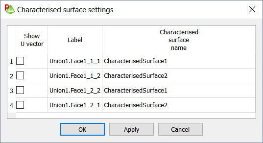
Each face that has a characterised surface applied to, is listed on the Characterised surface settings dialog. - For each face, you can select the Show U vector check box to show the direction in the 3D view.
-
Click OK to close the dialog.
The start of the vector (the coordinate system origin) is indicated by a yellow dot. The vector is displayed as a blue line to indicate that it is aligned with the U reference direction.