Modifying the Auto-Generated Mesh
When the frequency is set or local mesh settings are applied to the geometry, the automatic mesh algorithm calculates and creates the mesh automatically while the GUI is active using default mesh settings. When required, these mesh settings may be modified.
-
Open the Modify Mesh Settings dialog using one of the
following workflows:
- On the Mesh tab, in the
Meshing group, click the
 Modify Mesh icon.
 - Press Ctrl+M to use the keyboard shortcut.
- On the Mesh tab, in the
Meshing group, click the
- Set the Mesh size to Fine.
-
Set the Wire segment radius to
0.7.
Figure 1. The Modify Mesh Settings dialog. 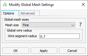
-
Click OK to create the mesh
and to close the dialog.
Figure 2. Top view of the patch and substrate showing the mesh. 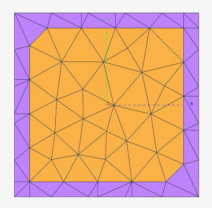
-
View the effect in the 3D view of specifying a Wire segment
radius.
-
Enable a default cutplane. In the model tree
(Construction tab), under
Cutplanes, click the
 icon next to
XZ‑Cut2 and from the right-click context menu, select Flip
cutplane.
icon next to
XZ‑Cut2 and from the right-click context menu, select Flip
cutplane.
Figure 3. Note that a cutplane icon is greyed out when the cutplane is not active. 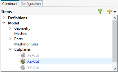
Figure 4. The cutplane shows a cross-sectional view of the patch substrate. Note the thick feedpin as specified by the Wire segment radius. 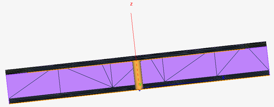
-
Disable the cutplane. Click the button next to XZ-Cut
again.
-
Enable a default cutplane. In the model tree
(Construction tab), under
Cutplanes, click the
1 See the Feko User Guide Appendix A-3 for more information regarding
automatic mesh sizes.
2 To change the default cutplane
settings, double-click on the cutplane text (for example,
XZ-Cut).