Setting Local Mesh Sizes for Chamfered Edges
Refine the mesh locally at the chamfered edges.
The mesh can be refined globally but will result in an unnecessary large number of mesh elements. A more efficient approach is to only refine the mesh locally where a finer mesh is required.
Note: Local mesh refinement takes precedence over global mesh settings.
-
In the 3D view, select a chamfered edge.
Figure 1. Top view of patch and substrate. The blue edge indicates that it is selected. 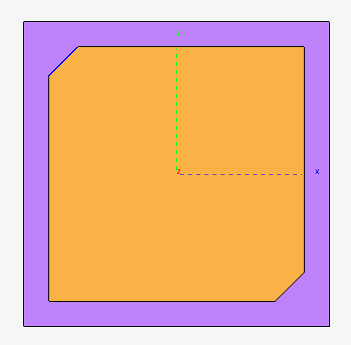
- From the right-click context menu, select Properties.
-
On the Modify Edge dialog (Meshing
tab), specify the following:
- Select the Local mesh size check box.
- Set the Mesh size to 2.
Figure 2. The Modify Edge (Meshing tab) dialog. 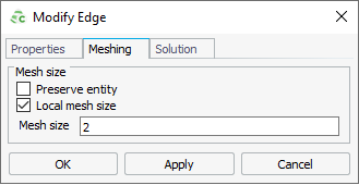
-
Repeat Step 1 to
Step 3 for the
second chamfered edge.
Figure 3. Top view of patch and substrate. The second chamfered edge is selected. 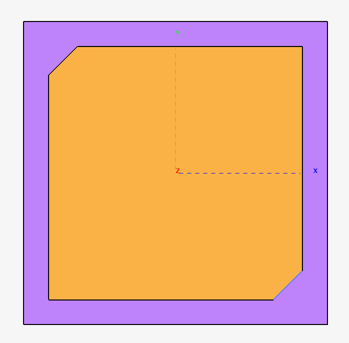
-
Click OK to apply the
properties and to close the dialog.
Figure 4. Top view of patch and substrate showing the localised mesh refinement at the chamfered edges. 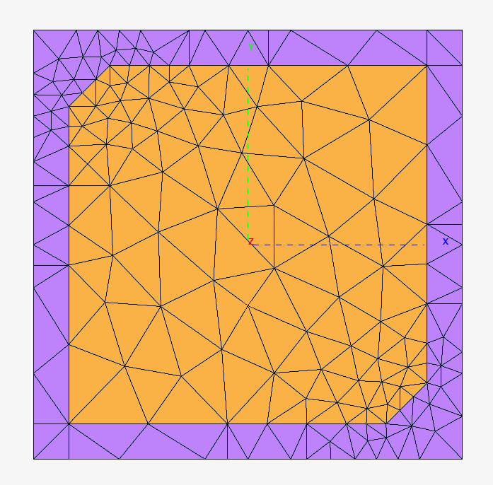
Note: The  icon in the details tree indicate that
a local mesh setting is applied.
icon in the details tree indicate that
a local mesh setting is applied.