Clinch Spacing
Check the clearance between clinch data.
Clinch is lead’s bending area on the DIP type component reverse side.
The Clinch Spacing dialog contains the following
sections:
- Clearance between Clinch to Patterns
- Clearance between DIP Type Components’ Clinch and Routing Pattern: Set the clearance value between the clinch and routing pattern.
- Exceptional Group: Select void-checking component group. PollEx DFM skips these components in checking.
- Do not check Clearance with same Net’s Routing Patterns: PollEx DFM doesn’t check clearances between the clinch and routing patterns with the same net name.
- Clearance between Clinches
- Target Component’s Placed Layer: Select the layers where the target components are placed.
- Setting: Set layers, reset the clinch table or set the clinch clearance value as a proper value at the same time.
- Clinch Layer Define: Use the button menu to set the layer where the
clinch data exists. If reserving clinch in Component Overlap Check
(COC) data in design, it’s possible to use it. Additionally, if the
clinch is drawn in some layers for the top and bottom, define them
using the following methods.
Figure 1. 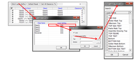
- Default Reset: Reset table to default setup status. Component classes checking combination and clearance value are reset.
- Set All Clearance To: Set all clearance values with given value.
- Clinch Table: Table contains all defined component class combinations and clearance values.
- Exclude Checking for Components, having different Property Values:
This is a selection of void-checking components in clinch clearance
checking.
- Property: Use the
 button to
select the property. After comparing property contents, for
components having different property contents, PollEx DFM skips them in checking.
button to
select the property. After comparing property contents, for
components having different property contents, PollEx DFM skips them in checking.
- Property: Use the